Operation
5.4pH Sensor Setup Menu (continued)
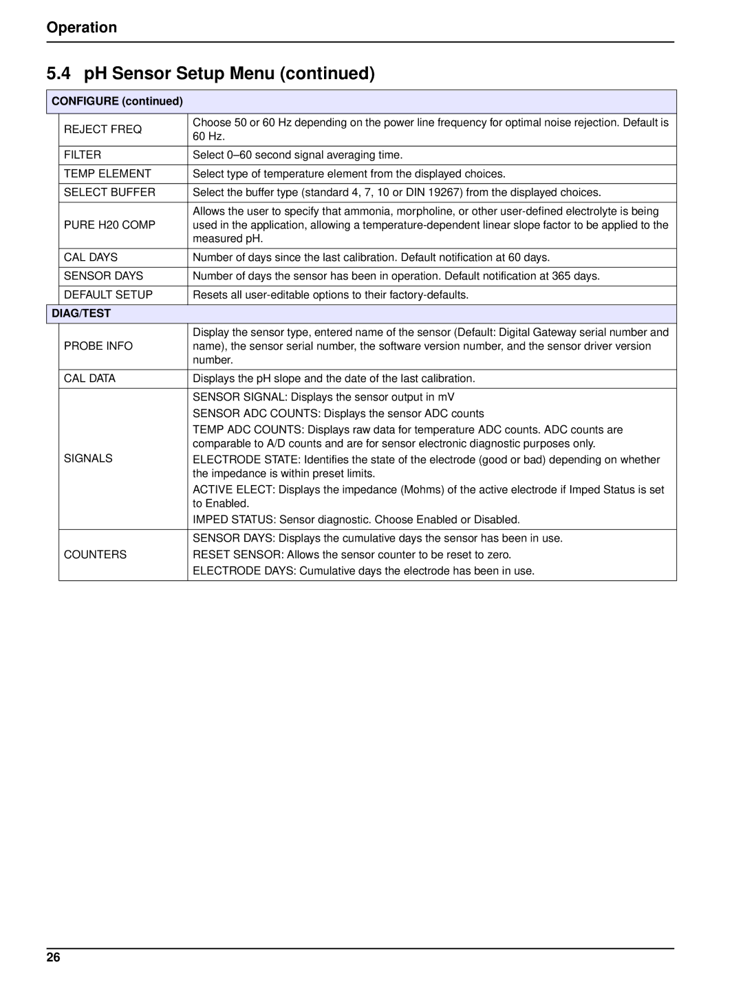
CONFIGURE (continued)
| REJECT FREQ | Choose 50 or 60 Hz depending on the power line frequency for optimal noise rejection. Default is |
| 60 Hz. | |
|
| |
|
|
|
| FILTER | Select |
|
|
|
| TEMP ELEMENT | Select type of temperature element from the displayed choices. |
|
|
|
| SELECT BUFFER | Select the buffer type (standard 4, 7, 10 or DIN 19267) from the displayed choices. |
|
|
|
|
| Allows the user to specify that ammonia, morpholine, or other |
| PURE H20 COMP | used in the application, allowing a |
|
| measured pH. |
|
|
|
| CAL DAYS | Number of days since the last calibration. Default notification at 60 days. |
|
|
|
| SENSOR DAYS | Number of days the sensor has been in operation. Default notification at 365 days. |
|
|
|
| DEFAULT SETUP | Resets all |
|
|
|
DIAG/TEST |
| |
|
| Display the sensor type, entered name of the sensor (Default: Digital Gateway serial number and |
| PROBE INFO | name), the sensor serial number, the software version number, and the sensor driver version |
|
| number. |
|
|
|
| CAL DATA | Displays the pH slope and the date of the last calibration. |
|
|
|
|
| SENSOR SIGNAL: Displays the sensor output in mV |
|
| SENSOR ADC COUNTS: Displays the sensor ADC counts |
|
| TEMP ADC COUNTS: Displays raw data for temperature ADC counts. ADC counts are |
|
| comparable to A/D counts and are for sensor electronic diagnostic purposes only. |
| SIGNALS | ELECTRODE STATE: Identifies the state of the electrode (good or bad) depending on whether |
|
| the impedance is within preset limits. |
|
| ACTIVE ELECT: Displays the impedance (Mohms) of the active electrode if Imped Status is set |
|
| to Enabled. |
|
| IMPED STATUS: Sensor diagnostic. Choose Enabled or Disabled. |
|
|
|
|
| SENSOR DAYS: Displays the cumulative days the sensor has been in use. |
| COUNTERS | RESET SENSOR: Allows the sensor counter to be reset to zero. |
|
| ELECTRODE DAYS: Cumulative days the electrode has been in use. |
|
|
|
26