Detailed Installation Instructions
Detailed Installation
Instructions
General Installation Warnings
The following general warnings should be observed when installation and/or general service maintenance is performed.
•Plumbing connections should be done in accordance with state and local plumbing codes.
•Do not use with water that is microbiologically unsafe or of unknown quality without adequate disinfection before or after the system.
•Drain lines should be 1⁄2” minimum for drain line flows up to 7 gpm. Flows above 7 gpm or runs in excess of 20 feet require 3⁄4” drain line.
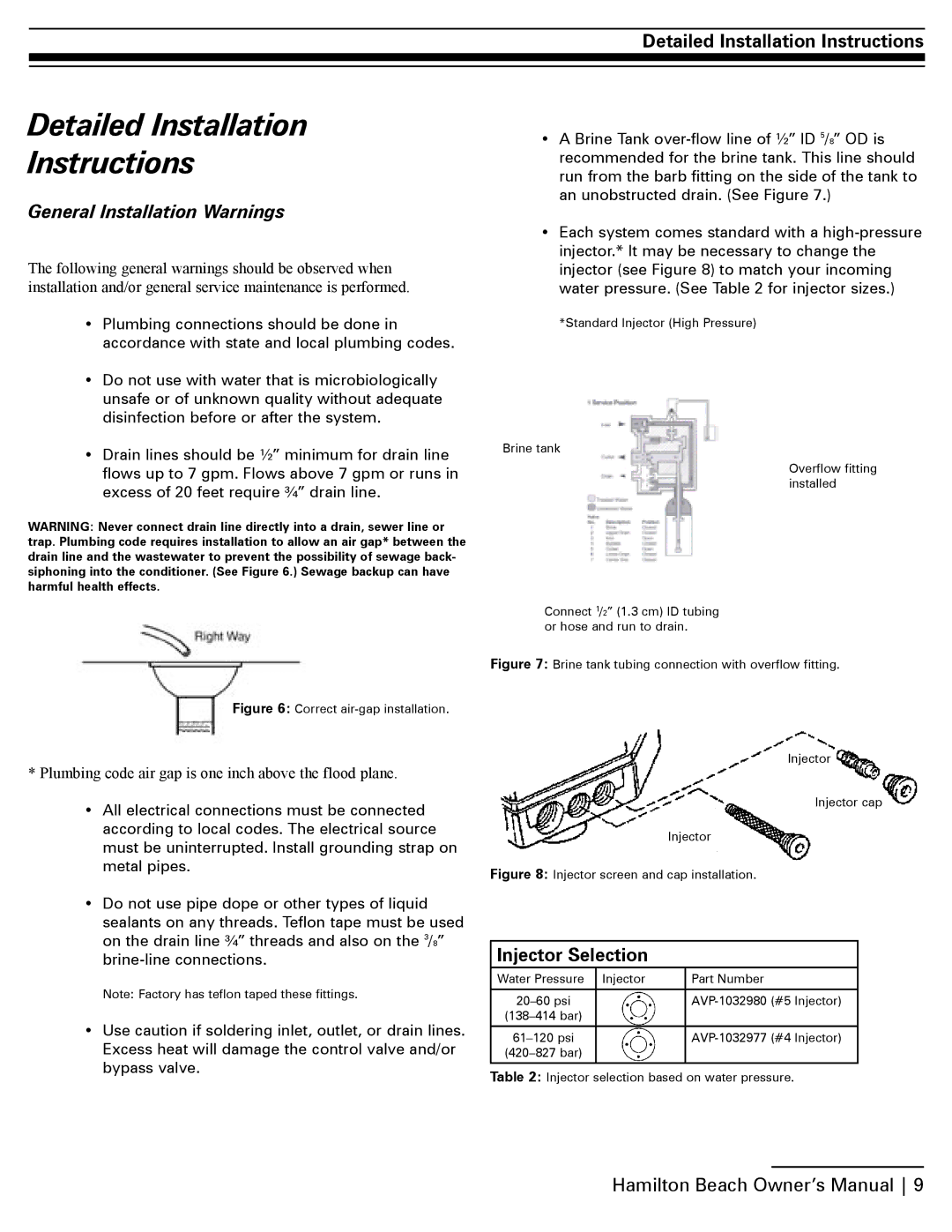
WARNING: Never connect drain line directly into a drain, sewer line or trap. Plumbing code requires installation to allow an air gap* between the drain line and the wastewater to prevent the possibility of sewage back- siphoning into the conditioner. (See Figure 6.) Sewage backup can have harmful health effects.
Figure 6: Correct air-gap installation.
*Plumbing code air gap is one inch above the flood plane.
•All electrical connections must be connected according to local codes. The electrical source must be uninterrupted. Install grounding strap on metal pipes.
•Do not use pipe dope or other types of liquid sealants on any threads. Teflon tape must be used on the drain line 3⁄4” threads and also on the 3/8”
Note: Factory has teflon taped these fittings.
•Use caution if soldering inlet, outlet, or drain lines. Excess heat will damage the control valve and/or bypass valve.
•A Brine Tank
•Each system comes standard with a
*Standard Injector (High Pressure)
Brine tank
Overflow fitting installed
Connect 1/2” (1.3 cm) ID tubing or hose and run to drain.
Figure 7: Brine tank tubing connection with overflow fitting.
Injector
Injector cap
Injector
Figure 8: Injector screen and cap installation.
Injector Selection
Water Pressure | Injector | Part Number |
|
|
|
| ||
|
| |
|
|
|
| ||
|
| |
|
|
|
Table 2: Injector selection based on water pressure.
Hamilton Beach Owner’s Manual 9