satellite receiver, cable set-top or HDTV tuner is in use if the digital audio is temporarily interrupted when channels are changed or when a cable box switches from a channel with a digital data stream to a channel with analog audio only. The UNLOCK message is normal, and does not indicate any problem with your receiver. Rather, it tells you that the incoming data has simply been paused or is not present for a variety of possible reasons.
When Dolby Digital 3/2/.1 or DTS 3/2/.1 signals are being played, the AVR will automatically switch to the proper surround mode, and no other processing may be selected. When a Dolby Digital signal with a 3/1/0 or 2/0/0 signal is detected you may select any of the Dolby sur- round modes.
Surround Mode Post Processing Thanks to the power of the AVR 147’s DSP processor, a variety of surround mode options are available for most digital signals to deliver either the native information or to produce an enhanced sound field to match the number of speakers in your system. The modes available and the number of channels available for each mode will vary depending on the incoming bitstream, and the configuration of your system, and are listed in the tables below. The modes may be selected in the usual manner by selecting the major Surround Mode Group first, and then scrolling through the options.
The incoming bitstreams are indicated in the Lower Display Line Ò as described above. After you have selected a surround mode, after about 5 seconds, the bitstream will be displayed briefly before the unit returns to normal opera- tion. Therefore, you may ascertain the current bit- stream simply by pressing the button for the major Surround Mode Group and waiting for a few moments for the bitstream to appear in the Lower Display Line Ò. The bitstream informa- tion will also be displayed after the source input has been changed.
To use the table below, match the indication in the display to the Incoming Bitstream listed in the left column. The available surround modes are shown to the right.
It is always a good idea to check the readout for the channel data to make certain that it matches the audio logo information shown on the back of a DVD package. In some cases you will see indi- cation for “2/0/0” even when the disc contains a full 5.1, or 3/2/.1 signal. When this happens, check the audio output settings for your DVD player or the audio menu selections for the spe- cific disc being played to make certain that the player is sending the correct signal to the AVR.
PCM Playback Indications
PCM is the abbreviation for Pulse Code Modulation, which is the type of digital signal used for standard CD playback, and other non- Dolby Digital and non-DTS digital sources such as Mini-Disc. When a PCM signal is detected, the Main Information Display Ò will briefly show a message with the letters PCM, in addition to a readout of the sampling frequency of the digital signal.
Connections may be made to either the rear- panel Optical or Coaxial Inputs or the front-panel Digital Inputs *Ó.
To listen to a PCM digital source, first select the input for the desired source (e.g., CD). Next press the Digital Select Button ÛG and then use the ⁄/¤ Buttons D on the remote, or the ‹/› Selector Buttons 7 on the front panel, until the desired choice appears in the Upper Display Line Ò.
During PCM playback, you may select any Surround mode except Dolby Digital or DTS, as shown in the table below. Note that for convenience, we have included the modes available for analog sources (including the tuner) in the chart on the bottom of this page.
In most cases this will be 48 KHZ, though in the case of specially mastered, high-resolution audio discs you will see a 96 KHZ indication.
The PCM 48 KHZ indication will also appear when modes or inputs are changed for analog sources. In those cases the system is telling you the sampling frequency used internally at the output of the analog-to-digital converters that change the incoming signal from a VCR, tape deck, the tuner, or other ana-log source to digital.
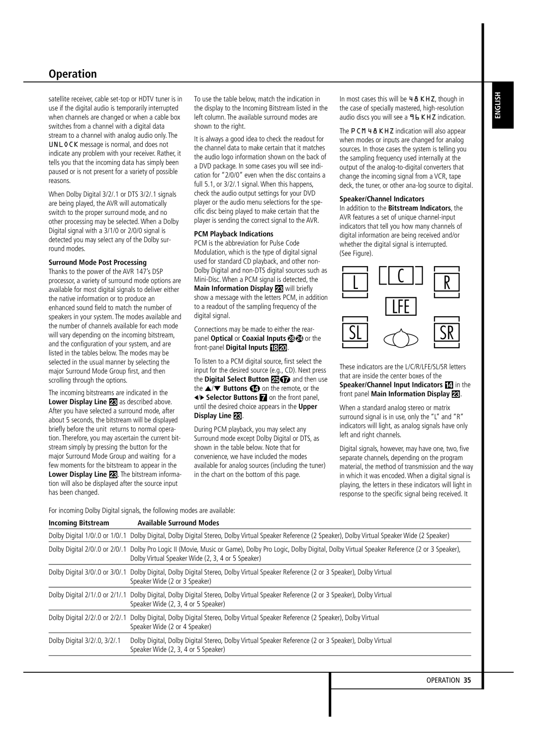
Speaker/Channel Indicators
In addition to the Bitstream Indicators, the AVR features a set of unique channel-input indicators that tell you how many channels of digital information are being received and/or whether the digital signal is interrupted.
(See Figure).
These indicators are the L/C/R/LFE/SL/SR letters that are inside the center boxes of the Speaker/Channel Input Indicators $ in the front panel Main Information Display Ò.
When a standard analog stereo or matrix surround signal is in use, only the “L” and “R” indicators will light, as analog signals have only left and right channels.
Digital signals, however, may have one, two, five separate channels, depending on the program material, the method of transmission and the way in which it was encoded. When a digital signal is playing, the letters in these indicators will light in response to the specific signal being received. It
For incoming Dolby Digital signals, the following modes are available:
Incoming Bitstream | Available Surround Modes |
Dolby Digital 1/0/.0 or 1/0/.1 Dolby Digital, Dolby Digital Stereo, Dolby Virtual Speaker Reference (2 Speaker), Dolby Virtual Speaker Wide (2 Speaker)
Dolby Digital 2/0/.0 or 2/0/.1 Dolby Pro Logic II (Movie, Music or Game), Dolby Pro Logic, Dolby Digital, Dolby Virtual Speaker Reference (2 or 3 Speaker), Dolby Virtual Speaker Wide (2, 3, 4 or 5 Speaker)
Dolby Digital 3/0/.0 or 3/0/.1 Dolby Digital, Dolby Digital Stereo, Dolby Virtual Speaker Reference (2 or 3 Speaker), Dolby Virtual Speaker Wide (2 or 3 Speaker)
Dolby Digital 2/1/.0 or 2/1/.1 Dolby Digital, Dolby Digital Stereo, Dolby Virtual Speaker Reference (2 or 3 Speaker), Dolby Virtual Speaker Wide (2, 3, 4 or 5 Speaker)
Dolby Digital 2/2/.0 or 2/2/.1 Dolby Digital, Dolby Digital Stereo, Dolby Virtual Speaker Reference (2 Speaker), Dolby Virtual Speaker Wide (2 or 4 Speaker)
Dolby Digital 3/2/.0, 3/2/.1 Dolby Digital, Dolby Digital Stereo, Dolby Virtual Speaker Reference (2 or 3 Speaker), Dolby Virtual Speaker Wide (2, 3, 4 or 5 Speaker)