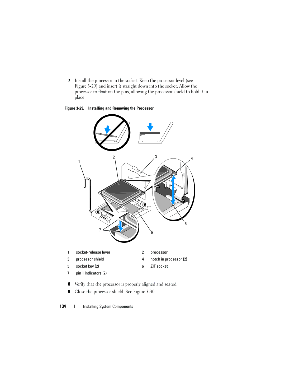
7Install the processor in the socket. Keep the processor level (see Figure
Figure 3-29. Installing and Removing the Processor
2 | 3 | 4 |
1
|
|
| 5 |
| 7 |
| 6 |
|
|
| |
1 |
| 2 | processor |
3 | processor shield | 4 | notch in processor (2) |
5 | socket key (2) | 6 | ZIF socket |
7 | pin 1 indicators (2) |
|
|
8Verify that the processor is properly aligned and seated.
9Close the processor shield. See Figure
134
