6If not already done, route the interface and RAID battery cables in the cable path inside the right interior wall of the chassis beneath the cable retention bracket. See "Cable Routing" and Figure
7Connect the SAS A cable to the SAS A connector on the backplane and, if applicable, connect the SAS B cable to the SAS B connector on the backplane.
8Close the system. See "Closing the System."
9Reconnect your system and peripherals to their electrical outlets, and turn on the system.
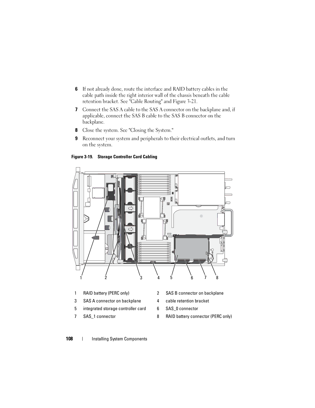
Figure 3-19. Storage Controller Card Cabling
1 | 2 | 3 | 4 | 5 | 6 | 7 | 8 |
1 | RAID battery (PERC only) |
| 2 | SAS B connector on backplane | |||
3 | SAS A connector on backplane | 4 | cable retention bracket |
| |||
5 | integrated storage controller card | 6 | SAS_0 connector |
|
| ||
7 | SAS_1 connector |
| 8 | RAID battery connector (PERC only) | |||