Motorola
Proprietary Material
LGEN031@email.mot.com
Fast’R
Basic Modem Setup
Advanced Modem Setup
Troubleshooting Problems and Improving Performance
Appendix B. Attention AT Commands
Fast’RVu
Appendix A. Regulatory Information
Appendix C. Specifications
Return Procedures Index
Appendix D. Four-Button/LCD User Interface
Page
About This Guide Introduction
Mise en Garde
Audience
Other Documentation
Vorsicht
¡Precaución
Avertissement
Warnung
Trademarks
Windows
Page
To Access the Motorola World-Wide Web Site
Motorola Customer Information
To Order Additional Motorola User Documentation
Page
Excellent Good Average Below Average Poor
Part Number T0022-01, Rev F
Business Reply Mail
Chapter Hardware Installation
Fast’R
Installing a Stand-Alone Modem
Installing a Stand-Alone Modem
Step Action
RJ11 Telco
For two-wire leased-line or dial-line modems
For two- or four-wire leased-line/dial-line modems
Ferrite Bead Installation
Modem Rear Panel and Cable Connections
Transformer
Safety and Operational Notices
Power Transformer
Connecting Ports
Repair
Lightning
Installing an AccessWay Enclosure
Checking AccessWay Enclosure Shipment
Site and Power Preparation
Computer Cable for Fast’RVu
Cooling for One or Two Enclosures
Cooling for Three or More Enclosures
Fan and Deflector Requirements
Cabinet Arrangement- Three or More Enclosures
Selecting a Power Cord
Power Cord and Plug Standards Countries
Group Country
Installing the Enclosure in an Equipment Rack
Installing an AccessWay in an Equipment Rack
Cabling an AccessWay Enclosure
Cabling an AccessWay Enclosure
Attached Motorola network management system NMS
Cabling One or More Enclosures to a Computer
Cabling Enclosures Together for Fast’RVu
NMS or Fast’RVu
First Enclosure Locations Second Enclosure Locations
Third Enclosure Locations
Fourth Enclosure Locations
Modem Addresses in Multiple-Enclosure Configurations
Installing/Removing Modem Cards
Installing a Modem Card
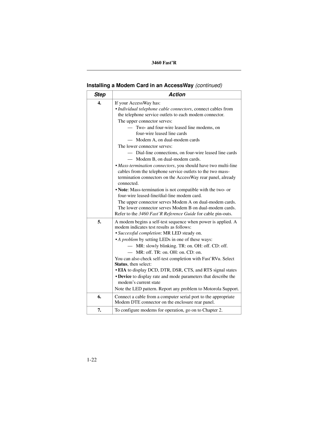
Installing a Modem Card in an AccessWay
Two-Wire Leased- or
Individual telephone cable connectors, connect cables from
Removing a Modem Card from an AccessWay
Removing a Modem Card
Power Modules
AC Power Module
DC Power Module
Connecting to DC Power Supply
Connecting the AccessWay to DC Power Supply
12. Replace the power module
12. Power Module Alarm Circuit Switches
Tip for Power Module Setup
4 cm
Installing a Second DC Power Module
Installing a Second DC Power Module
14. Dual DC Power Module Locations
Power Module Location Two Slots
Installing a Modem Daughtercard, Vanguard Enclosure
Set-Up
Page
Vanguard Daughtercard Setup
Before You Start
Entering Commands to the Modem
Setting Up for Asynchronous Dial Operation
Asynchronous Operation
Step Stage
Basic Setup for Sync Leased-Line Operation
Leased-Line Synchronous Operation
Fax Setup on Windows
Installing a Modem on a Windows Computer
Install and run a fax application
Page
Chapter Advanced Modem Setup
Modem Configuration and Commands
What is the Configuration?
Issuing AT Commands
Issuing Network Management Commands
What Are Option Sets?
Configuring a Modem for Async Operation
Managing Option Sets
Selecting and Customizing Option Set
Configuring a Modem for Leased-Line Sync Operation
Option-Set Parameter Default Options
Threshold DTR Delay
Pstn Signaling
Modulation Mode
Data Transfer Mode
AT Commands for Modem Tasks
AT Commands to Manage Option Sets Enter This
AT Action Commands
AT Action Commands Command & Option Description
Dial Modifiers
Dial Modifiers Description
Site-Specific Parameters Default Option Available Option
Non-Option Set Parameters
Terminal Options
Telco or Telco Jack Options
Dial Line Filter
Dialing Options
Access Security Options
Remote Configuration Options
Option Set Options
Restoral Options
DTR/ACU
Other Options
Access Security Functions
Password Verification on Connection
Configuration and Phone Number Access Restriction
Access Security AT Command Summary
Security Parameters, Default Options Command Description
Outbound Dial Restriction
Quiet Answer
Configuring a Remote Modem AT*RA
Running a Remote Configuration Session
Step Stage
Network Management AT*NE
Managing Remote Modems in an AccessWay Enclosure
Managing Remote Modems
AT*NP Parameter Options
Option Description
Configuring Modems for Restoral
Parameter Option Comment
AT*DI1=Low/Fast
Dial line as soon as it connects
Often the modem checks for loop
Page
Chapter Fast’RVu
Getting Started With Fast’RVu
Closing Multiple Fast’RVu Windows
Language Options
Specifying a Modem in Fast’RVu
Adding a Display Language to Fast’RVu
Specifying a Modem On Which to Operate Fast’RVu
Fast’RVu main window, select
Useful Information
Do This
Viewing and Setting Modem Options
Example Setting Callback to Phonebook Entry
Checking Device, Circuit, and Signal Status
Example Checking Device Status
Entering Commands
This Command Submenu Lets You
Example Copying a Configuration From One Modem to Another
Example Executing a Bit Error Rate BER Test
Executing Line and Modem Tests
Using Fast’RVu to Communicate With a Remote Modem
Network Management Override
Problems During a Download
Downloading Modem Software
Downloading Modem Software with Fast’RVu
Chapter Troubleshooting Problems Improving Performance
Troubleshooting Steps
Troubleshooting Actions
Installation
Call Establishment
Fast’R
Data Mode
Fast’R
Call Termination
File Transfer Mode
LEASED-LINE Operation
Running Diagnostic Tests
Test Description Command
Appendix a
This Appendix
EEC Directive Conformity
For Pstn Operation in Portugal
Fast’R
Regulatory Marking
Country Statutory Statements Canada
Industry Canada Equipment Attachment Limitations
Canadian Emission Statements
Country Statutory Statements U. K
Country Statutory Statements U. S. a
FCC Part 68 Registration Information
FCC Part 15 Emission Statements
Fast’R
Product Safety Regulatory Marking
AT Command Set
Command Option Description
Echo Async AT Commands to Terminal
Speaker Volume
Enter On-Line Data Mode
Busy Out Test
Select Pulse Dialing
Display Result Code
Store Value in S-Register
Select Tone Dialing
Commands
Break-Signal Receipt Handling
Call-Answering Mode
No-Buffering Mode
Select Connect Message
Default Telephone Number to Dial When DTR
Receive-Data Buffer Delay
108=On
Data Compression
Dial Wait Period Pause After Dialing
DTE Computer Port Rate
Data Mode for Direct Mode
Leased to Dial Threshold
Error Correction Protocol
Automatically Redial Failed Calls
Transmit Level for Dialed Calls
Flow Control Protocol
Hold Dial Line
Dial to Leased Threshold
Dial Line Filter
Link Telephone Numbers
Low-Speed Operation Protocol
LXn Transmit Level for Leased-Line Calls
Pstn Signaling
Modulation Mode
Minimum Rate
AT Message
Maximum Rate
Network Control NC Address
Buffer Option
Display Stored Telephone Number
Network Control Override Mode
Secondary Channel
Network Control Pass Through
Password Protection Enable/Disable
Password Protection Lock
Password Protection Unlock
Password Change
Abort Remote Configuration
Initiate/Terminate Restoral
Parity
Restoral Auto-Redial
Data Transfer Mode
Auto Retrain
Modem Speed Bar Display
Test Restoral
Call Time-Out
25bis Synchronizing Idle Signal
25bis Character Code
25bis Format
25bis Response
Enter Access Security Group Password
Callback After Incoming Call
Dial Restriction
Require Remote Telephone Number
Verify Password
DCD Control
DTR Control
Re-Initialize Memory Now
Guard Tone
Display Modem ID
Line Type
Pulse Cycle
CTS Control
DSR Control
Clock Signal Source
Test
Status Message
Save Changes
Power Up in Option Set
Service Class
Select Phonebook Entry to Enter
+FCLASS=n Service Class
+FCR=n Receive Fax Data
+FLO=n Fax Flow Control
Manufacturer ID
Software Revision Level
+FPR=n Serial Port Rate
Command Default Register Parameter Value Description
Options Stored in Status S- Registers
Delay=S38
AT*DB3
Pin 22, where asserted means
Enable restoral indicator on EIA
Restoral is active
Result Messages and Codes
Numeric
Text Form
Call Progress Result Codes
Connect
Connect Message Result Codes, Reliable=Short
Connect Message Result Codes, Reliable=Long
Connect Reliable EC=x DC=y
EC=x DC=y
Miscellaneous Result Codes
Test Pattern Result Code
Fax Class 1 Result Codes
+F4
Page
Appendix C
Physical Characteristics
Modem Stand Daughter Property Card AccessWay Alone
Physical Properties
Vanguard
Operating Modes
Data Operation
Fax Operation Standards
Modulation Modes
Condition Modem Card AccessWay Stand-Alone
Condition Modem Card AccessWay Alone
Environmental Limits
Operating Conditions
Electromagnetic Compatibility
AccessWay Enclosure Power Supply and Power Requirements
AC Power Supply Module
DC Power Supply Module
AccessWay Enclosure Power and Modem Operation
AccessWay Enclosure and Network Management
Connectors and Interfaces
Interface RJ-11
Pin Function
Interface RJ-21X
Computer Interface Pin-outs Signal Number Circuit Function
Pin
Function
RJ-11 Interface Pin-outs Function
Mass-Termination Interface Pin-outs
Pin Function
Power Interface Power Type Connector
Changing a Configuration With the OLC Button
Network Management Interface Pin-outs
Pin Signal
Pin Two-Wire Function Four-Wire Function
Network Management Interface Pin-outs
Interface RJ-11 Connection Type Dial Line Pin Function
Stand-Alone Modem Connectors and Interfaces
Computer Interface Pin Circuit Function
LINE* Connector
Interface RJ-11 Connection Type Telephone Pin Function
Network Management Interface Pinouts
NMS OUT
Power Requirements
Requirement at Main Characteristic Supply Modem Input
Figure D-2. Stand-Alone Modem Front Panels
Status LEDs Light Bars
Figure D-3. Card Modem Front Panels
Status LEDs
Status LED Displays
Off
Light Bars
Light Bar Displays This Indicates
Compatibility
326X Leased-Line Operation Note
Page
Appendix D
Configuration OPT’S
Menu Organization-Categories Parameters, and Options
Using the Front-Panel User Interface
LCD Display
Control Buttons
Front-Panel Control Buttons
Down
Enter
Return Procedures Introduction
Equipment Return Procedures
Case of Damage
To Return Equipment For locations Contact
Factory Repair
Packaging Guidelines for Equipment Return
Symbols
Numerics
INDEX-2
INDEX-3
INDEX-4
INDEX-5
INDEX-6
INDEX-7
INDEX-8
INDEX-9
INDEX-10
INDEX-11
INDEX-12