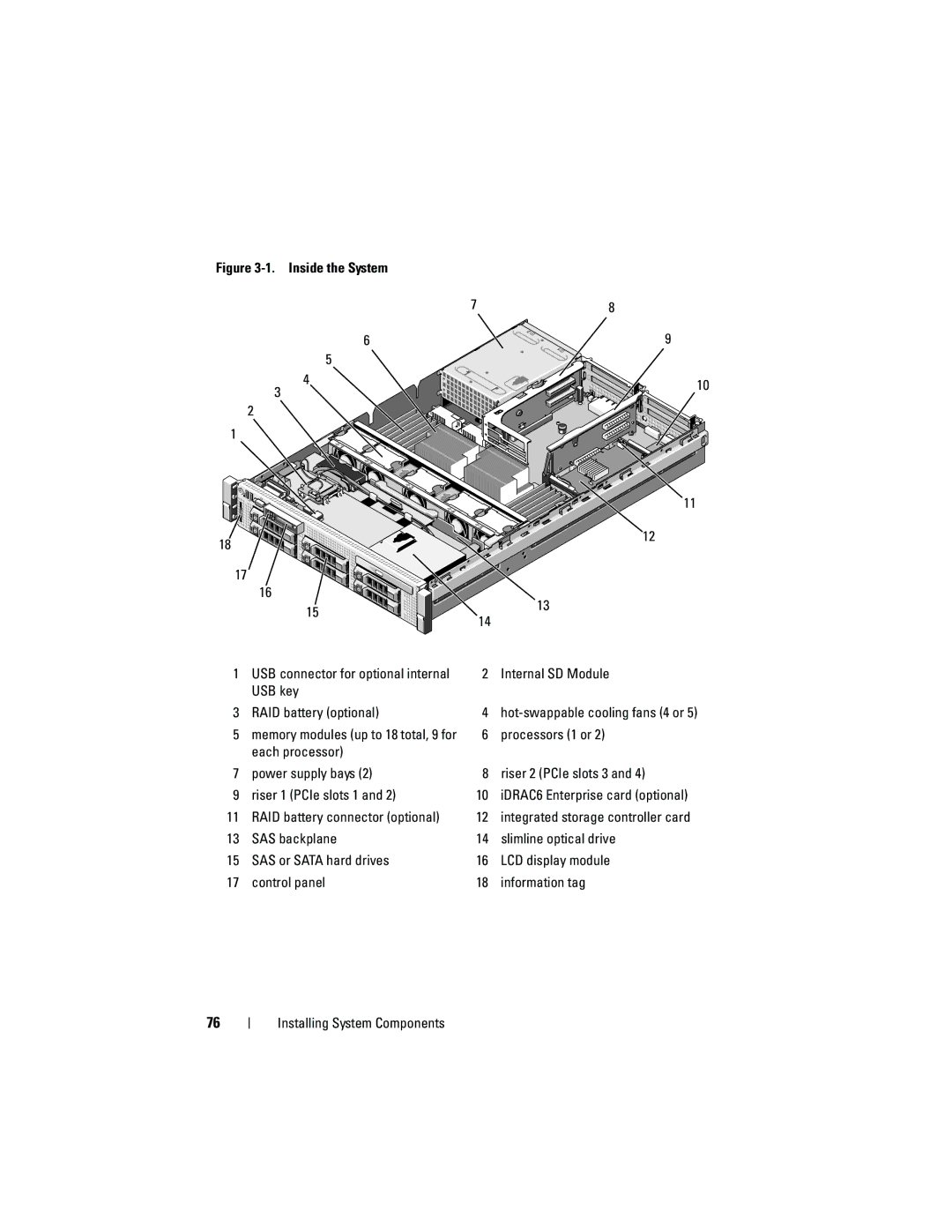
Figure 3-1. Inside the System
6
5
4 3
2 1
18
17![]() 16
16
15
7
14
8
9
10
![]() 11
11
![]() 12
12
![]() 13
13
1USB connector for optional internal USB key
3 RAID battery (optional)
5memory modules (up to 18 total, 9 for each processor)
7 power supply bays (2)
9 riser 1 (PCIe slots 1 and 2)
11RAID battery connector (optional)
13SAS backplane
15SAS or SATA hard drives
17control panel
2 Internal SD Module
4hot-swappable cooling fans (4 or 5)
6processors (1 or 2)
8 riser 2 (PCIe slots 3 and 4)
10iDRAC6 Enterprise card (optional)
12integrated storage controller card
14slimline optical drive
16LCD display module
18information tag
76