Part Names and Functions |
|
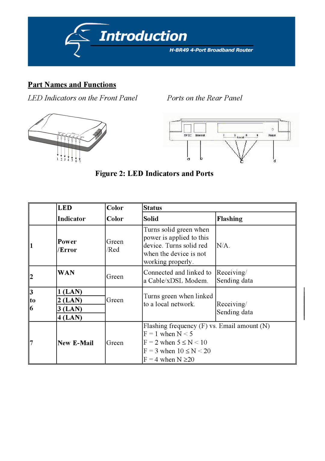
LED Indicators on the Front Panel | Ports on the Rear Panel |
1 2 3 4 5 6 7
Figure 2: LED Indicators and Ports
| LED | Color | Status |
| |
| Indicator | Color | Solid | Flashing | |
|
|
|
|
| |
|
|
| Turns solid green when |
| |
1 | Power | Green | power is applied to this |
| |
device. Turns solid red | N/A. | ||||
/Error | /Red | ||||
| when the device is not |
| |||
|
|
|
| ||
|
|
| working properly. |
| |
2 | WAN | Green | Connected and linked to | Receiving/ | |
| a Cable/xDSL Modem. | Sending data | |||
|
|
| |||
|
|
|
|
| |
3 | 1 (LAN) |
| Turns green when linked |
| |
to | 2 (LAN) | Green | Receiving/ | ||
to a local network. | |||||
6 | 3 (LAN) |
| |||
|
| Sending data | |||
| 4 (LAN) |
|
| ||
|
|
|
| ||
|
|
| Flashing frequency (F) vs. | Email amount (N) | |
|
|
| F = 1 when N < 5 |
| |
7 | New | Green | F = 2 when 5 ≤ N < 10 |
| |
|
|
| F = 3 when 10 ≤ N < 20 |
| |
|
|
| F = 4 when N ≥20 |
|
