1. Top Vent - Horizontal Termination - (continued)
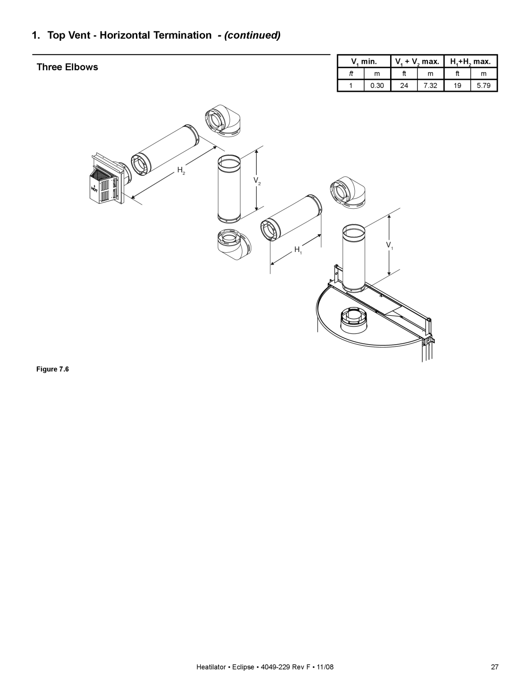
Three Elbows
V1 min. | V1 + V2 max. | H1+H2 max. | |||
ft | m | ft | m | ft | m |
1 | 0.30 | 24 | 7.32 | 19 | 5.79 |
H2
V2
H1V1
Figure 7.6
Heatilator • Eclipse • | 27 |
V1 min. | V1 + V2 max. | H1+H2 max. | |||
ft | m | ft | m | ft | m |
1 | 0.30 | 24 | 7.32 | 19 | 5.79 |
H2
V2
H1V1
Figure 7.6
Heatilator • Eclipse • | 27 |