E. Vent Diagrams
To replace the first starter elbow with two 45° elbows, refer to Figure 7.4. All other 90° elbows can be replaced with two 45° elbows.
General Rules:
•SUBTRACT 3 ft. from the total H measurement for each 90° elbow installed horizontally.
•SUBTRACT
•A maximum of three 90° elbows (or six 45° elbows) may be used in any vent configuration. Some elbows may be installed horizontally. See Figure 7.9.
•Elbows may be placed back to back anywhere in the system as long as the first 90° elbow is a starter elbow except as shown in Figure 7.4.
•When penetrating a combustible wall, a wall shield firestop must be installed on both sides.
•When penetrating a combustible ceiling, a ceiling firestop must be installed.
•Horizontal runs of vent do not require vertical rise; horizontal runs may be level.
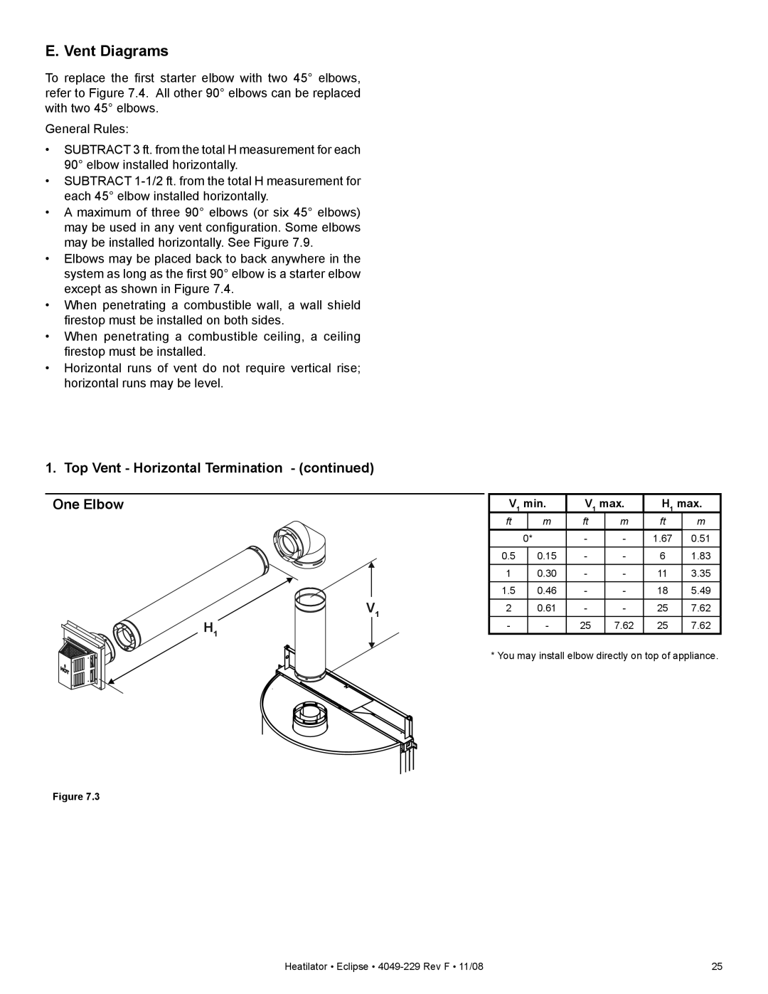
1. Top Vent - Horizontal Termination - (continued)
One Elbow |
| V1 min. | V1 max. | H1 max. | |||||
|
|
| ft |
| m | ft | m | ft | m |
|
|
|
| 0* | - | - | 1.67 | 0.51 | |
|
|
|
|
|
|
|
|
| |
|
|
| 0.5 |
| 0.15 | - | - | 6 | 1.83 |
|
|
| 1 |
| 0.30 | - | - | 11 | 3.35 |
|
|
| |||||||
|
|
|
|
|
|
|
|
|
|
|
|
| 1.5 |
| 0.46 | - | - | 18 | 5.49 |
V1 |
|
|
|
|
|
|
| ||
2 |
| 0.61 | - | - | 25 | 7.62 | |||
H1 |
|
| - |
| - | 25 | 7.62 | 25 | 7.62 |
|
| * You may install elbow directly on top of appliance. | |||||||
|
|
| |||||||
Figure 7.3
Heatilator • Eclipse • | 25 |