Install Horizontal Termination Cap
WARNING! Risk of Fire! The telescoping flue section of the termination cap MUST be used when connecting vent.
•
Failure to maintain overlap may cause overheating and fire.
•Vent termination must not be recessed in the wall. Siding may be brought to the edge of the cap base.
•Flash and seal as appropriate for siding material at outside edges of cap.
•When installing a horizontal termination cap, follow the cap location guidelines as prescribed by current ANSI Z223.1 and
CAUTION! Risk of Burns! Local codes may require installation of a cap shield to prevent anything or anyone from touching the hot cap.
NOTICE: For certain exposures which require superior resistance to
Note: When using termination caps with
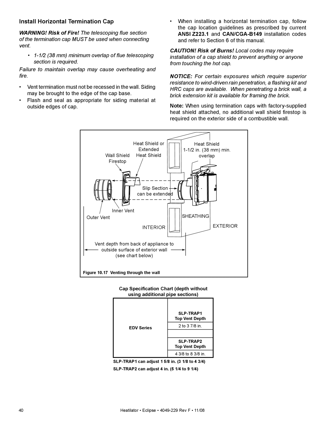
Heat Shield or | Heat | Shield |
Extended | ||
Wall Shield Heat Shield | overlap | |
Firestop |
|
|
Slip Section ![]() can be extended
can be extended
| Inner Vent | SHEATHING | ||
Outer Vent | ||||
| INTERIOR |
| EXTERIOR | |
Vent depth from back of appliance to |
|
| ||
| outside surface of exterior wall |
|
|
|
|
|
|
| |
| (see chart below) |
|
| |
Figure 10.17 Venting through the wall
Cap Specification Chart (depth without
using additional pipe sections)
EDV Series
Top Vent Depth
2 to 3 7/8 in.
SLP-TRAP2
Top Vent Depth
4 3/8 to 8 3/8 in.
40 | Heatilator • Eclipse • |