E. Electrical Service and Repair
WARNING! Risk of Shock! Label all wires prior to disconnection when servicing controls. Wiring errors can cause improper and dangerous operation. Verify proper operation after servicing.
WARNING! Risk of Shock! Replace damaged wire with type 105° C rated wire. Wire must have high temperature insulation.
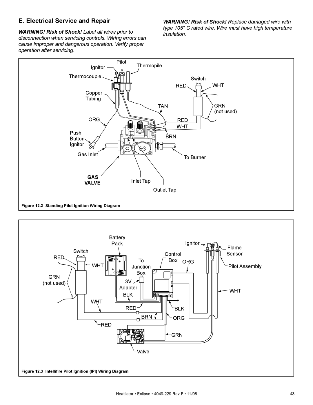
Ignitor | Pilot | Thermopile |
|
|
| ||
|
|
| |
Thermocouple |
|
| Switch |
|
|
| |
|
| RED | WHT |
Copper |
|
|
|
Tubing |
|
|
|
|
| TAN | GRN |
|
|
| (not used) |
ORG |
| RED |
|
Push |
| WHT |
|
| BRN |
| |
Button |
|
|
Ignitor
Gas Inlet | To Burner | |
| ||
GAS | Inlet Tap | |
VALVE | ||
Outlet Tap | ||
| ||
Figure 12.2 Standing Pilot Ignition Wiring Diagram |
|
Battery |
| Ignitor | |||
Pack |
|
| |||
Switch |
|
|
| Flame | |
|
| Control | Sensor | ||
RED |
|
| |||
+ | To | Box | ORG | ||
- | |||||
WHT | - | Junction |
| Pilot Assembly | |
+ | Box |
|
| ||
GRN |
|
|
| ||
| 3V |
|
| ||
(not used) |
|
|
| ||
| Adapter |
| WHT | ||
|
| BLK |
| ||
|
|
|
| ||
WHT |
| RED |
|
| |
|
| BLK | |||
BRN![]()
![]() ORG
ORG
![]() RED
RED
![]() GRN
GRN
![]() Valve
Valve
Figure 12.3 Intellifire Pilot Ignition (IPI) Wiring Diagram
Heatilator • Eclipse • | 43 |