3.To install the round support box/wall thimble cover in a flat ceiling, cut a 10 in. (254 mm) square hole in the ceiling, centered on the hole drilled in Step 2. Frame
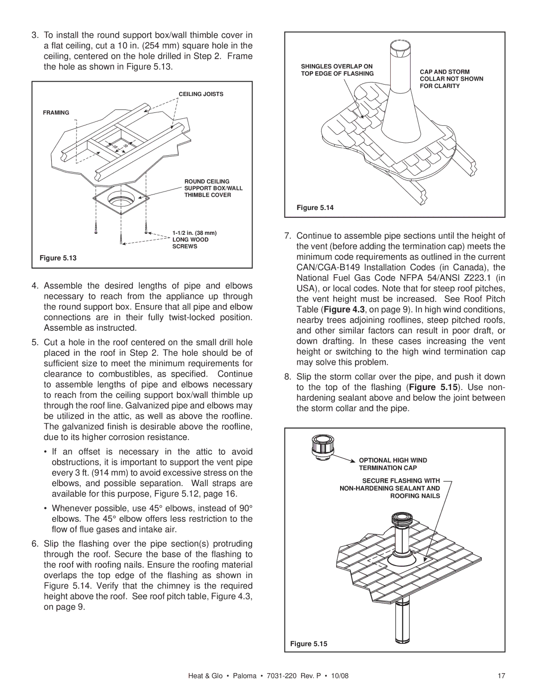
the hole as shown in Figure 5.13. | SHINGLES OVERLAP ON | CAP AND STORM |
| TOP EDGE OF FLASHING | |
|
| COLLAR NOT SHOWN |
|
| FOR CLARITY |
| CEILING JOISTS |
|
FRAMING |
|
|
ROUND CEILING
SUPPORT BOX/WALL
THIMBLE COVER
Figure 5.14
|
| 7. | Continue to assemble pipe sections until the height of | |||
| LONG WOOD |
| ||||
| SCREWS |
|
| the vent (before adding the termination cap) meets the | ||
| Figure 5.13 |
|
|
| minimum code requirements as outlined in the current | |
|
|
|
|
| ||
4. Assemble the desired lengths of | pipe and elbows |
| National Fuel Gas Code NFPA 54/ANSI Z223.1 (in | |||
| USA), or local codes. Note that for steep roof pitches, | |||||
| necessary to reach from the appliance up through |
| the vent height must be increased. | See Roof Pitch | ||
| the round support box. Ensure that all pipe and elbow |
| Table (Figure 4.3, on page 9). In high wind conditions, | |||
| connections are in their fully |
| nearby trees adjoining rooflines, steep pitched roofs, | |||
| Assemble as instructed. |
|
|
| and other similar factors can result in poor draft, or | |
5. | Cut a hole in the roof centered on the small drill hole |
| down drafting. In these cases increasing the vent | |||
| placed in the roof in Step 2. The hole should be of |
| height or switching to the high wind termination cap | |||
| sufficient size to meet the minimum requirements for |
| may solve this problem. |
| ||
| clearance to combustibles, as specified. | Continue | 8. | Slip the storm collar over the pipe, and push it down | ||
| to assemble lengths of pipe and elbows necessary |
| to the top of the flashing (Figure 5.15). Use non- | |||
| to reach from the ceiling support box/wall thimble up |
| hardening sealant above and below the joint between | |||
| through the roof line. Galvanized pipe and elbows may |
| the storm collar and the pipe. |
| ||
| be utilized in the attic, as well as above the roofline. |
|
|
| ||
| The galvanized finish is desirable above the roofline, |
|
|
| ||
| due to its higher corrosion resistance. |
|
|
|
| |
| • If an offset is necessary in the attic to avoid |
|
|
| ||
| obstructions, it is important to support the vent pipe |
| OPTIONAL HIGH WIND |
| ||
| every 3 ft. (914 mm) to avoid excessive stress on the |
| TERMINATION CAP |
| ||
|
| SECURE FLASHING WITH |
| |||
| elbows, and possible separation. | Wall straps are |
|
| ||
| available for this purpose, Figure 5.12, page 16. |
|
| |||
|
| ROOFING NAILS |
| |||
| • Whenever possible, use 45° elbows, instead of 90° |
|
|
| ||
| elbows. The 45° elbow offers less restriction to the |
|
|
| ||
| flow of flue gases and intake air. |
|
|
|
|
|
6. Slip the flashing over the pipe section(s) protruding |
|
|
| |||
| through the roof. Secure the base of the flashing to |
|
|
| ||
| the roof with roofing nails. Ensure the roofing material |
|
|
| ||
| overlaps the top edge of the flashing as shown in |
|
|
| ||
| Figure 5.14. Verify that the chimney is the required |
|
|
| ||
| height above the roof. See roof pitch table, Figure 4.3, |
|
|
| ||
| on page 9. |
|
|
|
|
|
|
|
|
| Figure 5.15 |
| |
|
| Heat & Glo • Paloma • | 17 | |||