|
| |
| TRANSFORMER | FLAME |
|
| |
ON/OFF | SPARKER/SENSOR | |
WALL |
| |
SWITCH |
| |
| IGNITION |
|
| MODULE |
|
| (3V) |
|
| VALVE | BATTERY |
| PACK | |
|
| REMOTE |
NEUTRAL | GROUND | CONTROL HOT |
|
| |
TRANSFORMER
3 VAC
PLUG IN
JUNCTION BOX
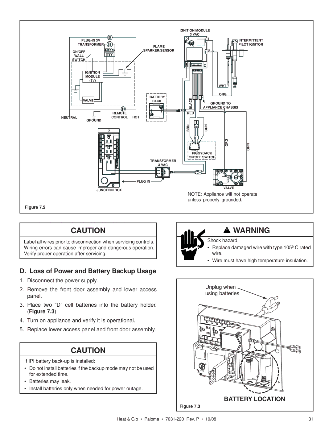
Figure 7.2
IGNITION MODULE
3 VAC
IINTERMITTENT PILOT IGNITOR
S
| WHT |
|
BLACK | ORG |
|
GROUND TO |
| |
APPLIANCE CHASSIS |
| |
RED | * |
|
|
| |
BRN | BRN |
|
| ORG | GRN |
|
| |
PIGGYBACK |
| |
ON/OFF SWITCH |
| |
VALVE
NOTE: Appliance will not operate unless properly grounded.
CAUTION
Label all wires prior to disconnection when servicing controls. Wiring errors can cause improper and dangerous operation. Verify proper operation after servicing.
![]() WARNING
WARNING
Shock hazard.
•Replace damaged wire with type 105º C rated wire.
•Wire must have high temperature insulation.
D. Loss of Power and Battery Backup Usage
1. | Disconnect the power supply. |
| Unplug when |
|
2. | Remove the front door assembly and lower access |
| ||
using batteries |
| |||
| panel. |
|
| |
|
|
|
| |
3. | Place two "D" cell batteries into | the battery holder. |
|
|
| (Figure 7.3) |
|
|
|
4. | Turn on appliance and verify it is operational. |
|
| |
5. | Replace lower access panel and front door assembly. |
|
| |
| CAUTION |
|
|
|
If IPI battery |
|
|
| |
• Do not install batteries if the backup mode may not be used |
|
| ||
| for extended time. |
|
|
|
• | Batteries may leak. |
|
|
|
• | Install batteries only when needed for power outage. |
|
| |
|
|
| BATTERY LOCATION |
|
|
|
| Figure 7.3 |
|
|
| Heat & Glo • Paloma • | 31 | |
