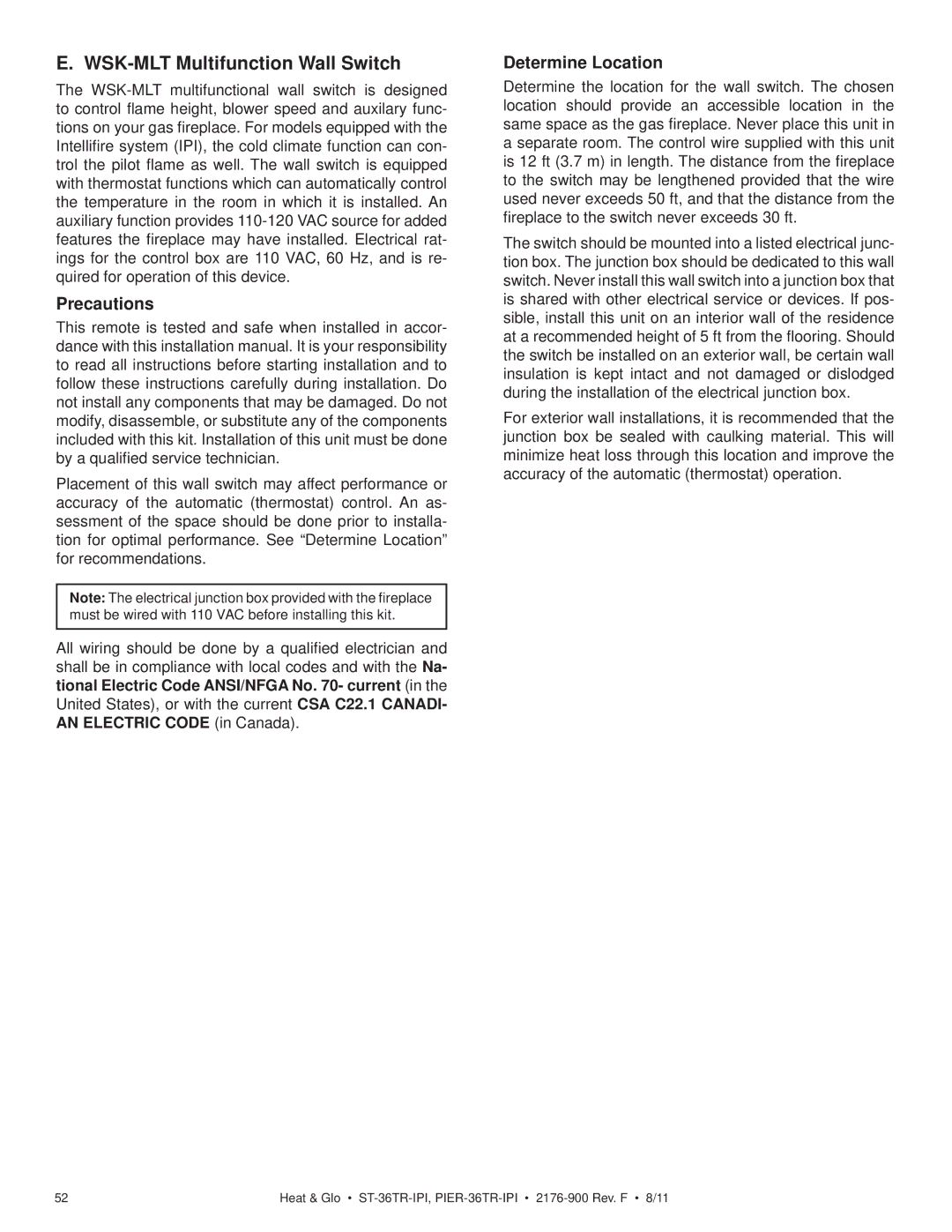
PIER-36TR-IPI, PIER-36TRLP-IPI, ST-36TRLP-IPI, ST-36TR-IPI specifications
Heat & Glo is renowned for its innovative and stylish fireplace solutions, and their LifeStyle series is no exception. The LifeStyle models, including the PIER-36TRLP-IPI, PIER-36TR-IPI, ST-36TRLP-IPI, and ST-36TR-IPI, are designed to provide both aesthetic appeal and unparalleled heating performance, making them perfect for a variety of living spaces.One of the defining features of these units is their contemporary design, which integrates seamlessly into modern interiors. The sleek, linear appearance allows for versatile installation options, whether in a wall or as a standalone feature. With a focus on maximizing visual impact, the large glass viewing area provides an unobstructed view of the flames, creating an inviting ambiance.
In terms of technology, these fireplaces are equipped with advanced ignition systems, specifically the IntelliFire® ignition system, which intelligently manages flame levels and optimizes efficiency. This technology not only aids in ease of use but also enhances safety, reducing the risk of unintended ignition.
The LifeStyle series also emphasizes energy efficiency. With an emphasis on reducing environmental impact, these fireplaces boast high efficiency ratings, ensuring that homeowners enjoy warmth without excessive energy consumption. The incorporation of direct vent technology allows for better heat retention indoors while drawing in fresh air from outside, minimizing drafts.
When it comes to performance, the LifeStyle models deliver reliable heating capabilities. Each unit is capable of producing up to 36,000 BTUs, ensuring sufficient warmth for medium to large spaces. This output, combined with adjustable flame height and ember bed options, allows users to customize their heating experience according to personal preferences.
Another characteristic of the LifeStyle series is the extensive range of aesthetically pleasing decorative options. Owners can select from various media, such as glass or ceramic logs, which add a touch of style to the fireplace while complementing the overall decor of the room.
Finally, easy maintenance is a hallmark of the LifeStyle series. Many components are designed for straightforward accessibility, making routine upkeep simple and hassle-free. This attention to practicality ensures that homeowners can enjoy their fireplace without the burden of complicated maintenance routines.
In summary, the Heat & Glo LifeStyle PIER and ST series combines elegant design, advanced technology, and efficient heating, making them a sought-after choice for homeowners looking to enhance their living spaces with a modern fireplace solution.
