Physical Data
|
|
|
|
|
| UNIT SIZE |
|
|
|
Description |
|
| 03 | 06 | 08 | 10 | 12 | 14 | 18 |
CFM Range* |
|
|
|
|
|
|
|
|
|
Cooling |
|
| |||||||
Heating & Ventilating |
| ||||||||
|
|
|
|
|
|
|
|
|
|
Fan Type & Shaft Diameter @ Bearing |
|
|
|
|
|
|
| ||
FC, Low Pres. | inches |
| 1 3/16 | 1 3/16 | |||||
FC, Med. Pres. | inches |
| 1 3/16 | 1 3/16 | 1 3/16 | 1 3/16 | 1 7/16 | 1 7/16 | |
AF, shaft dia. (in) @ bearing |
| — | — | — | — | — | — | — | |
|
|
|
|
|
|
|
|
|
|
Type 5 Coils |
|
|
|
|
|
|
|
|
|
Large | FH X FL |
| 18.00X24 | 21.00X39 | 30.00X36 | 30.00X45 | 33.00X51 | 33.00X60 | 42.00x60 |
Refrigerant | TH |
| 12T | 14T | 20T | 20T | 22T | 22T | 28T |
and Water Coils | FACE AREA |
| 3.00 | 5.69 | 7.50 | 9.38 | 11.69 | 13.75 | 17.50 |
Small | FH X FL |
| 12.00X24 | 15.00X39 | 24.00X36 | 24.00X45 | 27.00X51 | 27.00X60 | 36.00x60 |
Refrigerant | TH |
| 8T | 10T | 16T | 16T | 18T | 18T | 24T |
and Water Coils | FACE AREA |
| 2.00 | 4.06 | 6.00 | 7.50 | 9.56 | 11.25 | 15.00 |
Large Type 5 | FH X FL |
| 16.50X24 | 19.50X39 | 28.50X36 | 28.50X45 | 33.00X51 | 33.00X60 | 40.50x60 |
Steam Coils^ | TH |
| 11T | 13T | 19T | 19T | 22T | 22T | 27T |
| FACE AREA |
| 2.75 | 5.28 | 7.13 | 8.91 | 11.69 | 13.75 | 16.88 |
Small Type 5 | FH X FL |
| 12.00X24 | 15.00X39 | 24.00X36 | 24.00X45 | 24.00X51 | 27.00X60 | 34.50x60 |
Steam Coils^ | TH |
| 8T | 10T | 16T | 16T | 18T | 18T | 23T |
| FACE AREA |
| 2.00 | 4.06 | 6.00 | 7.50 | 9.56 | 11.25 | 14.38 |
|
|
|
|
|
|
|
|
|
|
Type A Coils |
|
|
|
|
|
|
|
|
|
Large | FH X FL |
| 18.75x24 | 21.25x39 | 31.25x36 | 31.25x45 | 35.00x51 | 35.00x60 | 42.50x60 |
Refrigerant | TH |
| 15T | 17T | 25T | 25T | 28T | 28T | 34T |
and Water Coils | FACE AREA |
| 3.13 | 5.76 | 7.81 | 9.77 | 12.40 | 14.58 | 17.71 |
Small | FH X FL |
| 12.50X24 | 16.25X39 | 25.00X36 | 25.00X45 | 28.75X51 | 28.75X60 | 35.00X60 |
Refrigerant | TH |
| 10T | 13T | 20T | 20T | 23T | 23T | 28T |
and Water Coils | FACE AREA |
| 2.08 | 4.40 | 6.25 | 7.81 | 10.18 | 11.99 | 14.58 |
Filters: |
|
|
|
|
|
|
|
|
|
| Area in Sq. Ft. |
| 5.00 | 6.94 | 10.00 | 11.11 | 15.00 | 17.50 | 22.50 |
Flat |
|
|
|
|
|
|
| ||
Section |
|
|
|
|
|
|
| ||
| Quantity and |
| 2- 20 X 25 | 2- 20 X 25 | |||||
| size |
|
|
| 3- 20X 20 | ||||
|
|
|
|
|
|
|
|
|
|
High | Area in Sq. Ft. |
| 10.00 | 13.89 | 16.67 | 19.44 | 22.22 | 25.00 | 37.50 |
Capacity |
|
|
|
|
|
|
|
|
|
Section | Quantity and |
| 4- 20 X 25 | ||||||
| size |
|
|
|
| ||||
|
|
|
|
|
|
|
|
|
|
High | Area in Sq. Ft. |
| 6.00 | 8.00 | 12.00 | 14.00 | 14.00 | 18.00 | 24.00 |
Efficiency |
|
|
|
|
|
|
|
|
|
Filter | Quantity and |
|
| ||||||
Section | size |
|
|
|
| ||||
|
|
|
|
|
|
|
|
|
|
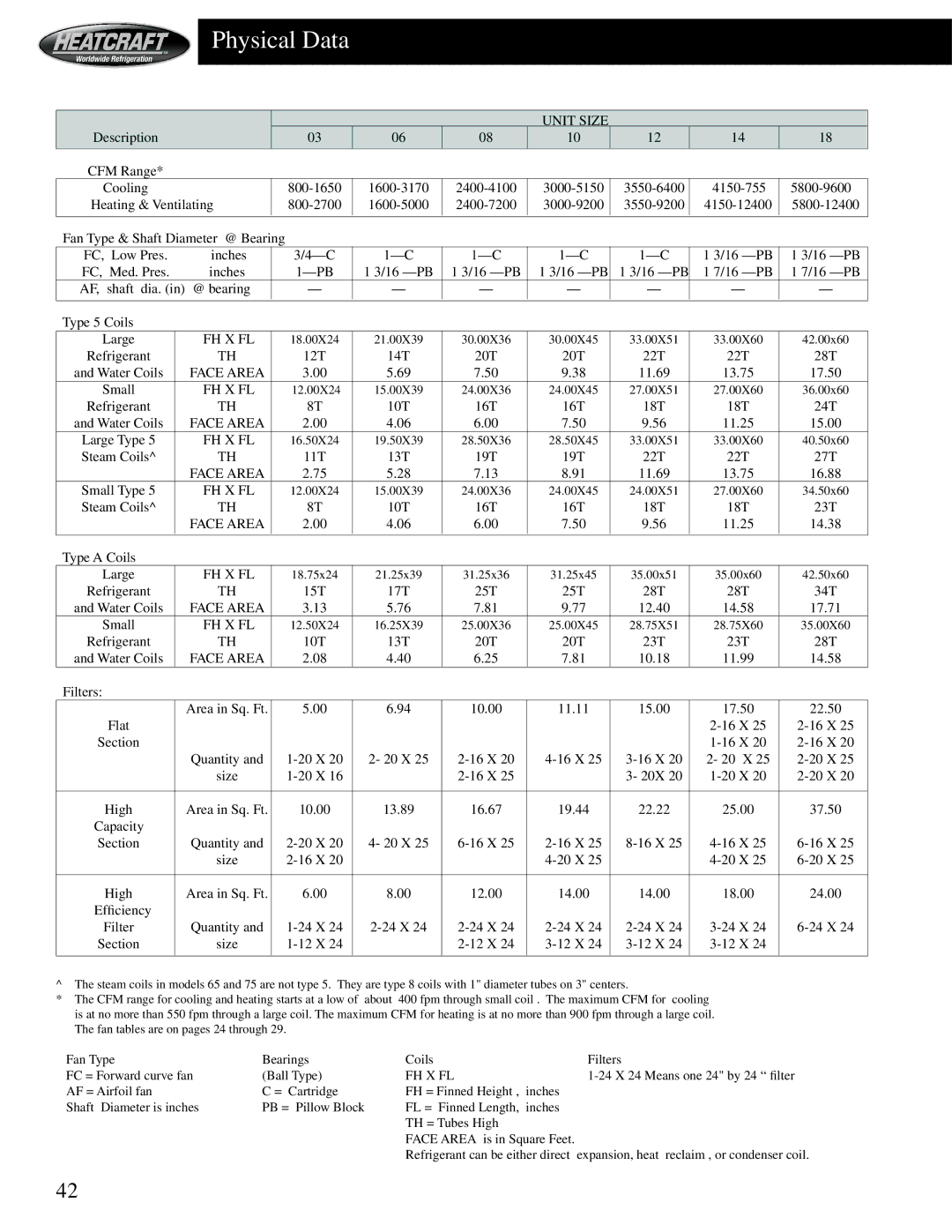
^The steam coils in models 65 and 75 are not type 5. They are type 8 coils with 1" diameter tubes on 3" centers.
*The CFM range for cooling and heating starts at a low of about 400 fpm through small coil . The maximum CFM for cooling is at no more than 550 fpm through a large coil. The maximum CFM for heating is at no more than 900 fpm through a large coil. The fan tables are on pages 24 through 29.
Fan Type | Bearings | Coils | Filters |
FC = Forward curve fan | (Ball Type) | FH X FL | |
AF = Airfoil fan | C = Cartridge | FH = Finned Height , inches |
|
Shaft Diameter is inches | PB = Pillow Block | FL = Finned Length, inches |
|
|
| TH = Tubes High |
|
|
| FACE AREA is in Square Feet. |
|
|
| Refrigerant can be either direct | expansion, heat reclaim , or condenser coil. |
42
