Henny PennyModel
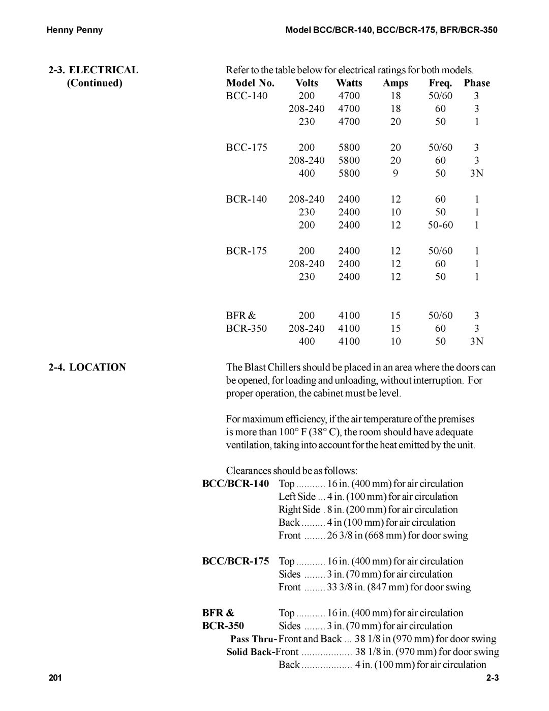
| Refer to the table below for electrical ratings for both models. | |||||
(Continued) | Model No. | Volts | Watts | Amps | Freq. | Phase |
| 200 | 4700 | 18 | 50/60 | 3 | |
|
| 4700 | 18 | 60 | 3 | |
|
| 230 | 4700 | 20 | 50 | 1 |
| 200 | 5800 | 20 | 50/60 | 3 | |
|
| 5800 | 20 | 60 | 3 | |
|
| 400 | 5800 | 9 | 50 | 3N |
| 2400 | 12 | 60 | 1 | ||
|
| 230 | 2400 | 10 | 50 | 1 |
|
| 200 | 2400 | 12 | 1 | |
| 200 | 2400 | 12 | 50/60 | 1 | |
|
| 2400 | 12 | 60 | 1 | |
|
| 230 | 2400 | 12 | 50 | 1 |
| BFR & | 200 | 4100 | 15 | 50/60 | 3 |
| 4100 | 15 | 60 | 3 | ||
|
| 400 | 4100 | 10 | 50 | 3N |
| The Blast Chillers should be placed in an area where the doors can | |||||
| be opened, for loading and unloading, without interruption. For | |||||
| proper operation, the cabinet must be level. |
|
| |||
For maximum efficiency, if the air temperature of the premises is more than 100° F (38° C), the room should have adequate ventilation, taking into account for the heat emitted by the unit.
Clearances should be as follows:
| Top | 16 in. (400 mm) for air circulation |
| Left Side ... | 4 in. (100 mm) for air circulation |
| Right Side . 8 in. (200 mm) for air circulation | |
| Back | 4 in (100 mm) for air circulation |
| Front | 26 3/8 in (668 mm) for door swing |
Top | 16 in. (400 mm) for air circulation | |
| Sides | 3 in. (70 mm) for air circulation |
| Front | 33 3/8 in. (847 mm) for door swing |
BFR & | Top | 16 in. (400 mm) for air circulation |
| Sides | 3 in. (70 mm) for air circulation |
Pass Thru- Front and Back ... 38 1/8 in (970 mm) for door swing | ||
Solid | 38 1/8 in. (970 mm) for door swing | |
| Back | 4 in. (100 mm) for air circulation |
201 |
