.A complete Parts List is available at www.HobartWelders.com
4-9. Selecting A Location And Connecting Input Power
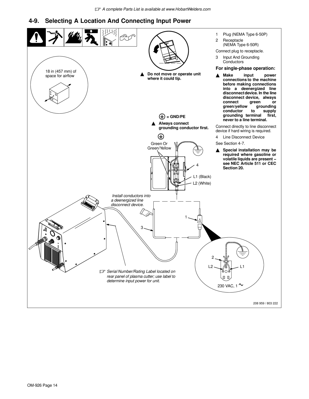
18 in (457 mm) of space for airflow
YDo not move or operate unit where it could tip.
 = GND/PE
YAlways connect grounding conductor first.
Green Or
Green/Yellow
![]() 4
4
L1 (Black)
![]() L2 (White)
L2 (White)
1Plug (NEMA Type
2Receptacle
(NEMA Type
Connect plug to receptacle.
3Input And Grounding Conductors
For single-phase operation:
Y Make input power connections to the machine before making connections into a deenergized line disconnect device. In the line disconnect device, always
connect green or
green/yellow grounding conductor to supply grounding terminal first, never to a line terminal.
Connect directly to line disconnect device if hard wiring is required.
4Line Disconnect Device See Section
YSpecial installation may be required where gasoline or volatile liquids are present − see NEC Article 511 or CEC Section 20.
Install conductors into a deenergized line disconnect device.
1
3
2
L2L1
.Serial Number/Rating Label located on
rear panel of plasma cutter; use label to determine input power for unit.
230 VAC, 1 ![]()
208 959 / 803 222