.A complete Parts List is available at www.HobartWelders.com
|
|
|
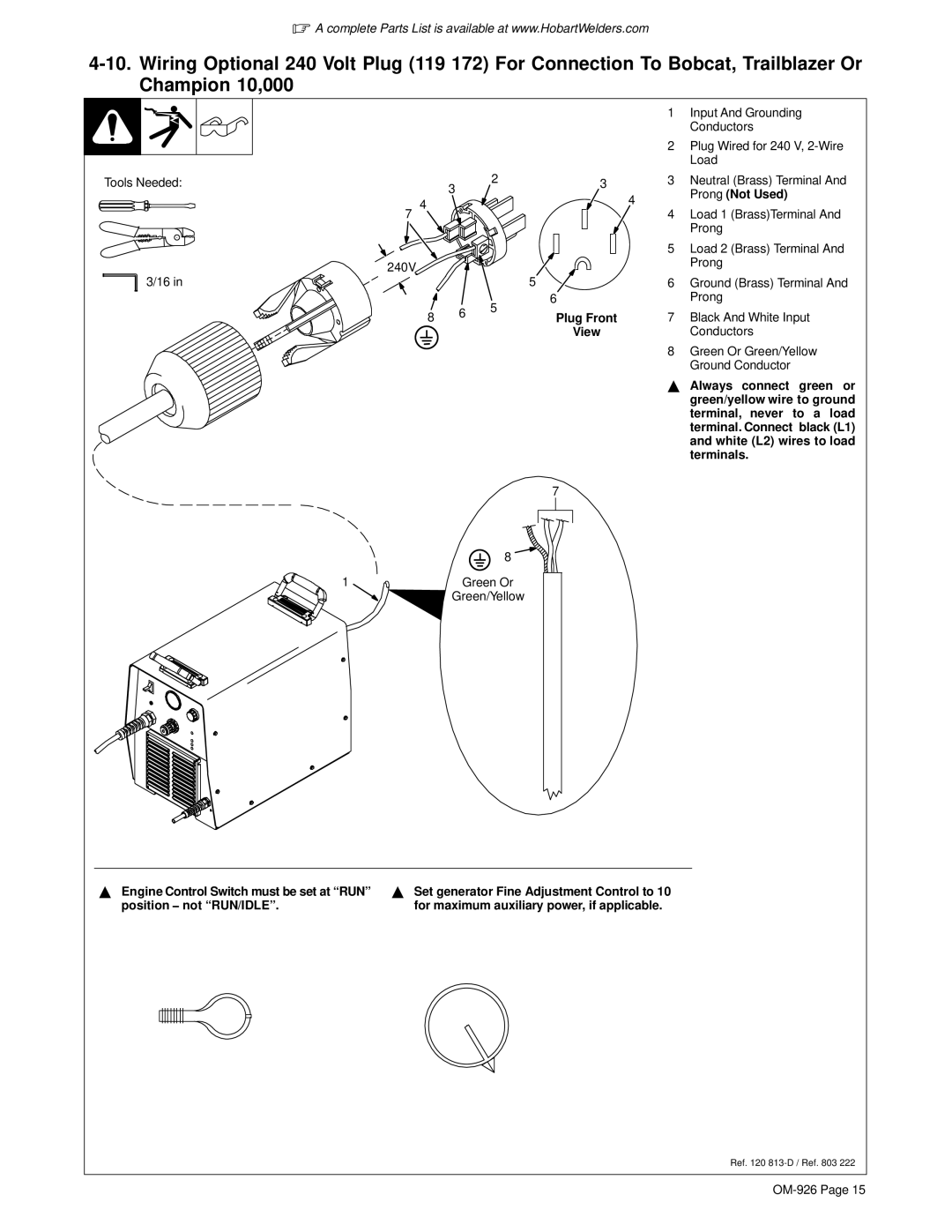
| 1 | Input And Grounding | |
|
|
|
|
| Conductors | |
|
|
|
| 2 | Plug Wired for 240 V, | |
|
|
|
|
| Load | |
Tools Needed: | 3 | 2 | 3 | 3 | Neutral (Brass) Terminal And | |
|
|
| 4 | Prong (Not Used) | ||
4 |
|
|
| |||
|
|
|
| |||
|
|
| 4 | Load 1 (Brass)Terminal And | ||
7 |
|
|
| |||
|
|
|
|
| Prong | |
|
|
|
| 5 | Load 2 (Brass) Terminal And | |
240V |
|
|
|
| Prong | |
|
|
|
|
| ||
3/16 in |
|
| 5 | 6 | Ground (Brass) Terminal And | |
|
| 5 | 6 |
| Prong | |
8 | 6 | Plug Front | 7 | Black And White Input | ||
| ||||||
|
| |||||
|
|
| View |
| Conductors | |
|
|
|
| 8 | Green Or Green/Yellow | |
|
|
|
|
| Ground Conductor | |
|
|
|
| Y Always connect green or | ||
|
|
|
|
| green/yellow wire to ground | |
|
|
|
|
| terminal, never to a load | |
|
|
|
|
| terminal. Connect black (L1) | |
|
|
|
|
| and white (L2) wires to load | |
|
|
|
|
| terminals. | |
|
|
| 7 |
|
| |
|
| 8 |
|
|
| |
1 | Green Or |
|
|
| ||
| Green/Yellow |
|
|
| ||
YEngine Control Switch must be set at “RUN” position − not “RUN/IDLE”.
YSet generator Fine Adjustment Control to 10 for maximum auxiliary power, if applicable.
Ref. 120
