Manuals
/
Hobart Welding Products
/
Power Tools
/
Welding System
Hobart Welding Products
OM-198 683C
manual
M-25 Gun
Models:
OM-198 683C
1
36
44
44
Download
44 pages
12.5 Kb
33
34
35
36
37
38
39
40
Troubleshooting
Specification
Install
Parts list
Error codes
Electrical Diagram
Symbol Usage
Threading Welding Wire
Safety
Turn Off power
Page 36
Image 36
16
15
13
14
9
11
12
9
10
11
12
8
7
6
17
5
4
3
2
1
Ref. 800
792-B
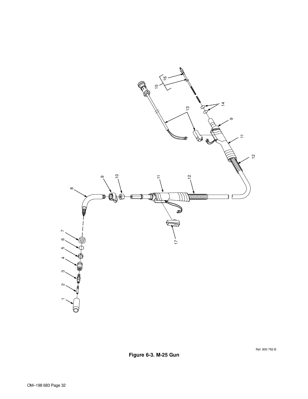
Figure
6-3.
M-25
Gun
OM–198
683 Page 32
Page 35
Page 37
Page 36
Image 36
Page 35
Page 37
Contents
OM-198 683C
Processes
Description
From Hobart to You
Table of Contents
Page
Symbol Usage
Marks a special safety message
Arc Welding Hazards
Electric Shock can kill
ARC Rays can burn eyes and skin
Welding can cause fire or explosion
Flying Metal can injure eyes
Buildup of GAS can injure or kill
Principal Safety Standards
EMF Information
About Pacemakers
Signification des symboles
Consignes DE Securite Lire Avant Utilisation
UN Choc É Lectrique peut tuer
LES Fumé ES ET LES GAZ peuvent ê tre dangereux
LE Soudage peut provoquer un incendie ou une explosion
DES Particules Volantes peuvent blesser les yeux
LE Bruit peut affecter l’ouïe
Risque D’INCENDIE OU
LA Chute DE L’APPAREIL peut blesser
’EMPLOI Excessif peut
DES Organes Mobiles peuvent provoquer des blessures
Principales normes de sé curité
Information sur les champs é lectromagné tiques
Consignes relatives aux stimulateurs cardiaques
Installation
Specifications
Welding Power Source Duty Cycle And Overheating
Exceeding duty cycle can damage unit and void warranty
Welding Gun Duty Cycle And Overheating
Volt-Ampere Curves
Definition
Installing Work Clamp
Installing Welding Gun
Connecting Olympic 30A Gun
Setting Gun Polarity For Wire Type
Installing Gas Supply
Installing Wire Spool and Adjusting Hub Tension
Positioning Jumper Links
Electrical Service Guide
Selecting a Location And Connecting Input Power
Threading Welding Wire
Scale
Weld Parameter
196
Operation
Controls
Voltmeter And Wire Feed Speed Meter Operation
Power Up Status
Error Message
Welding Status
Maintenance &TROUBLESHOOTING
Routine Maintenance
Circuit Breaker CB1
Unit Overload
Changing Drive Roll and Wire Inlet Guide
Turn Off power
Replacing Gun Contact Tip
Aligning Drive Rolls and Wire Guide
Cleaning Or Replacing Gun Liner
Disconnect gun from unit first
To Reassemble Gun
Replacing Switch And/Or Head Tube
Disconnect gun first
Troubleshooting
Trouble Remedy
OM-198 683
Electrical Diagram
Circuit Diagram
Parts List
Main Assembly
Dia Part Description Mkgs Quantity
Baffle, Center w/Components
Baffle, Center w/Components -1 Item
M-25 Gun
M-25 Gun -1 Item
Panel, Front w/Components -1 Item
Wire Drive And Gears -2 Item
Wire Drive And Gears
Drive Roll And Wire Guide Kits
Panel, Rear w/Components -1 Item
Page
Page
Service
Support
Contact your Distributor for
Hobart Welding Products
Top
Page
Image
Contents