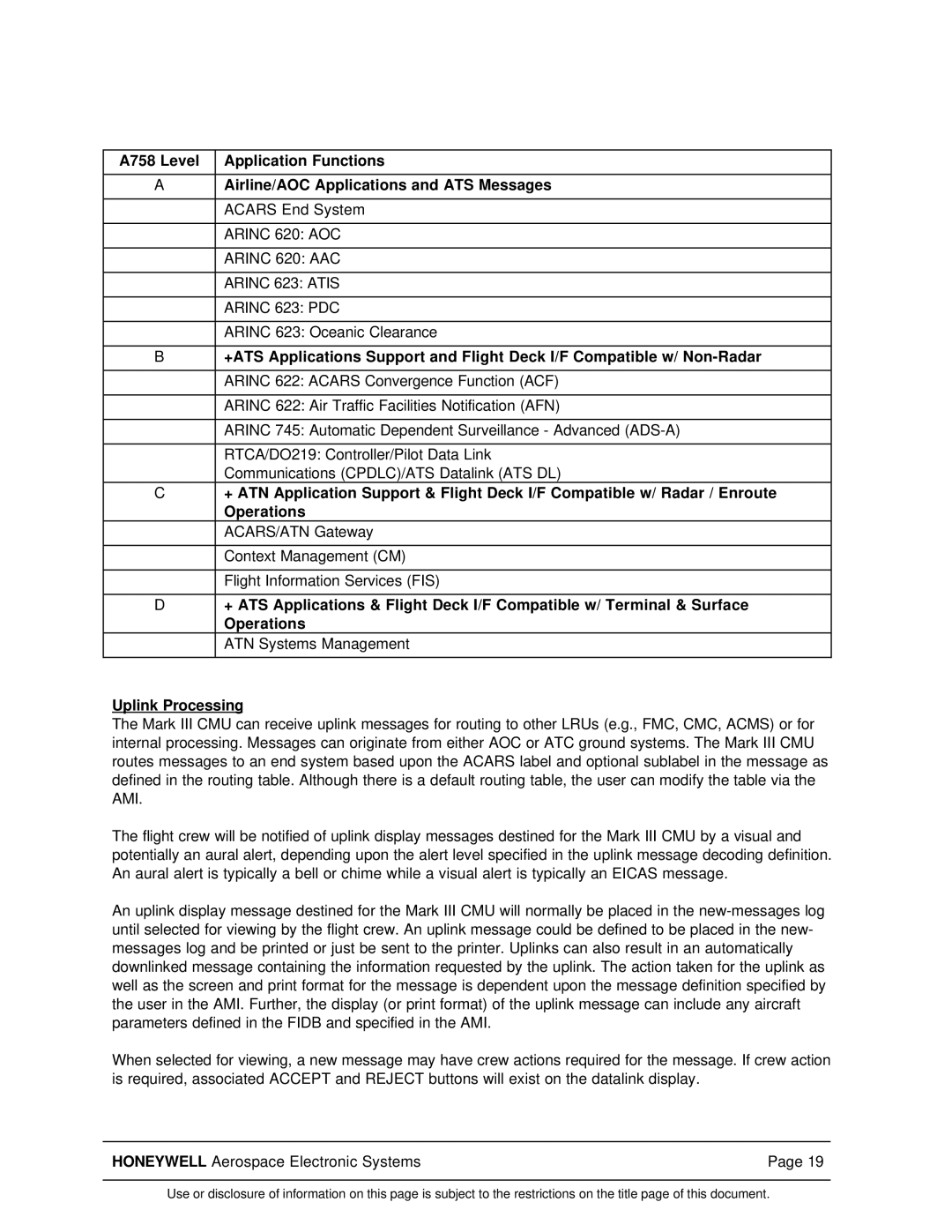
A758 Level | Application Functions |
|
|
A | Airline/AOC Applications and ATS Messages |
|
|
| ACARS End System |
|
|
| ARINC 620: AOC |
|
|
| ARINC 620: AAC |
|
|
| ARINC 623: ATIS |
|
|
| ARINC 623: PDC |
|
|
| ARINC 623: Oceanic Clearance |
|
|
B | +ATS Applications Support and Flight Deck I/F Compatible w/ |
|
|
| ARINC 622: ACARS Convergence Function (ACF) |
|
|
| ARINC 622: Air Traffic Facilities Notification (AFN) |
|
|
| ARINC 745: Automatic Dependent Surveillance - Advanced |
|
|
| RTCA/DO219: Controller/Pilot Data Link |
| Communications (CPDLC)/ATS Datalink (ATS DL) |
C | + ATN Application Support & Flight Deck I/F Compatible w/ Radar / Enroute |
| Operations |
| ACARS/ATN Gateway |
|
|
| Context Management (CM) |
|
|
| Flight Information Services (FIS) |
|
|
D | + ATS Applications & Flight Deck I/F Compatible w/ Terminal & Surface |
| Operations |
| ATN Systems Management |
|
|
Uplink Processing
The Mark III CMU can receive uplink messages for routing to other LRUs (e.g., FMC, CMC, ACMS) or for internal processing. Messages can originate from either AOC or ATC ground systems. The Mark III CMU routes messages to an end system based upon the ACARS label and optional sublabel in the message as defined in the routing table. Although there is a default routing table, the user can modify the table via the AMI.
The flight crew will be notified of uplink display messages destined for the Mark III CMU by a visual and potentially an aural alert, depending upon the alert level specified in the uplink message decoding definition. An aural alert is typically a bell or chime while a visual alert is typically an EICAS message.
An uplink display message destined for the Mark III CMU will normally be placed in the
When selected for viewing, a new message may have crew actions required for the message. If crew action is required, associated ACCEPT and REJECT buttons will exist on the datalink display.
HONEYWELL Aerospace Electronic Systems | Page 19 |
Use or disclosure of information on this page is subject to the restrictions on the title page of this document.
