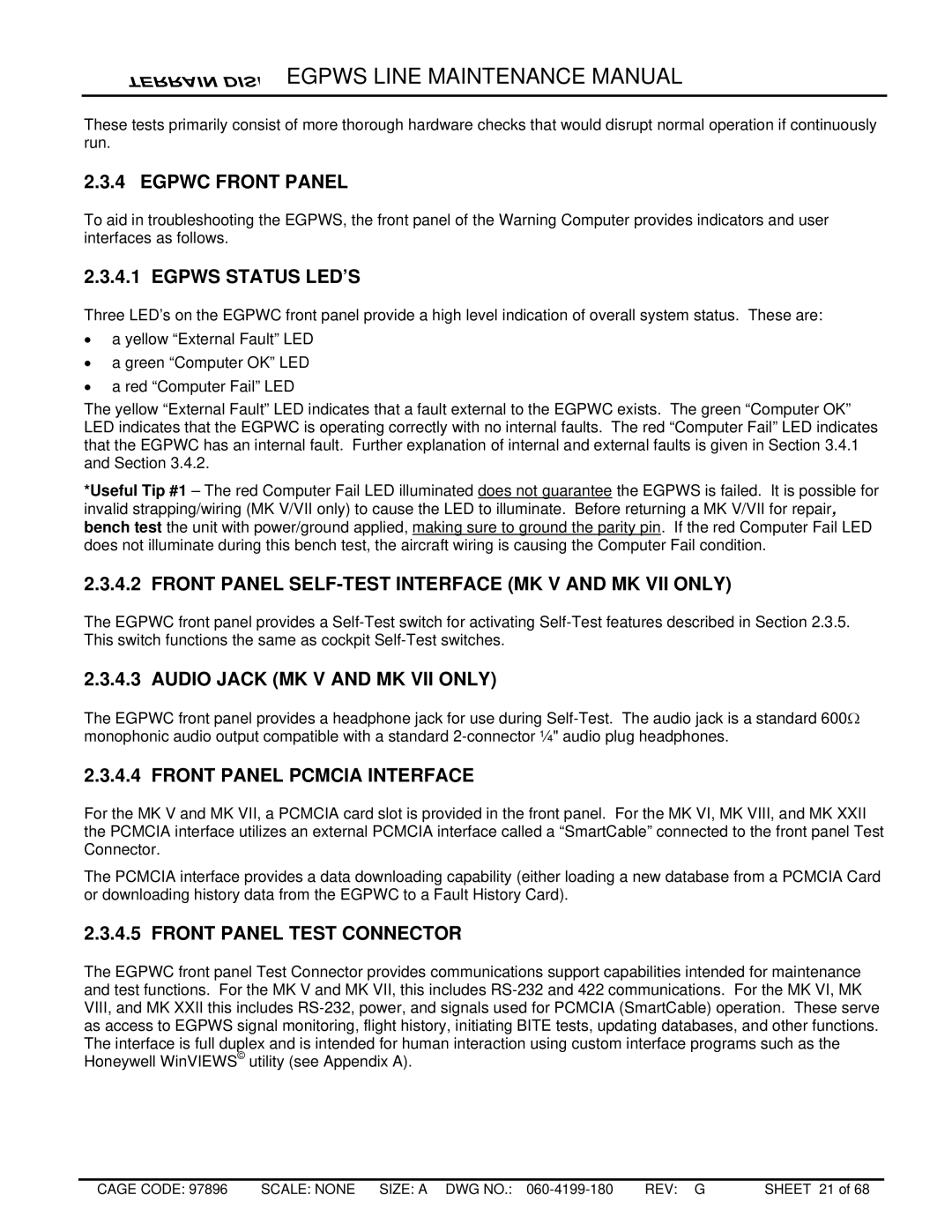
MK VIII, MK V, MK XXII, MK VII, MK VI specifications
Honeywell's range of control systems, particularly the MK VI, MK VIII, MK VII, V, and XXII, are pivotal innovations that have revolutionized process automation and control in various industries, especially in power generation and oil and gas sectors. Each of these systems comes with unique features and technologies to enhance operational efficiency, safety, and reliability.The Honeywell MK VI control system is renowned for its ability to provide effective plant control and management tools, featuring advanced operator interfaces and robust hardware components. It employs a modular design, which allows for easy scalability and integration into existing infrastructure. The MK VI is equipped with Ethernet-based communication protocols, ensuring high-speed data transfer and enabling seamless connectivity with other systems.
The MK VIII system takes automation a step further, emphasizing enhanced performance and reliability. With its built-in redundancy and advanced diagnostics, the MK VIII minimizes downtime and optimizes maintenance efforts. Its powerful software tools are designed to improve operator decision-making, providing critical insights into plant operations and trends.
Honeywell’s MK VII control system is designed for high-performance applications, especially in gas turbine environments. It features advanced control algorithms, enabling precise control of emissions and improving overall efficiency. The MK VII stands out with its ability to maintain optimal performance under varying load conditions, ensuring reliability in challenging operational scenarios.
The MK V system is one of Honeywell's legacy products, known for its simple and user-friendly interface. Despite its age, it continues to be a dependable choice for many plants. It offers solid performance with basic control functions and has been a reliable backbone for older facilities transitioning into newer technologies.
Lastly, the MK XXII brings a modern twist to control systems with its focus on cybersecurity and data analytics. This system takes advantage of big data and IoT technologies, providing enhanced visibility of operations through real-time monitoring and predictive maintenance capabilities. The MK XXII ensures that plants not only operate efficiently but also mitigate risks associated with cyber threats.
Overall, Honeywell's series of control systems showcases their commitment to innovation and reliability in process automation, catering to the diverse needs of contemporary industrial environments. Each system is designed with specific features and capabilities that address the evolving challenges of process control, ensuring that users can achieve optimal performance and safety in their operations.
