Maintenance and Service Guide
Product notice
Safety warning notice
Iii
Iv Safety warning notice
Table of contents
Sata data cable
System board callouts
104
100
103
105
124
120
121
Viii
Product description
Product description
Serviceability End user replaceable parts
SoftPaq
Product Features
Standard Configuration Features
Mm Microphone Jack
Front panel components
Front panel components
Power cord connector
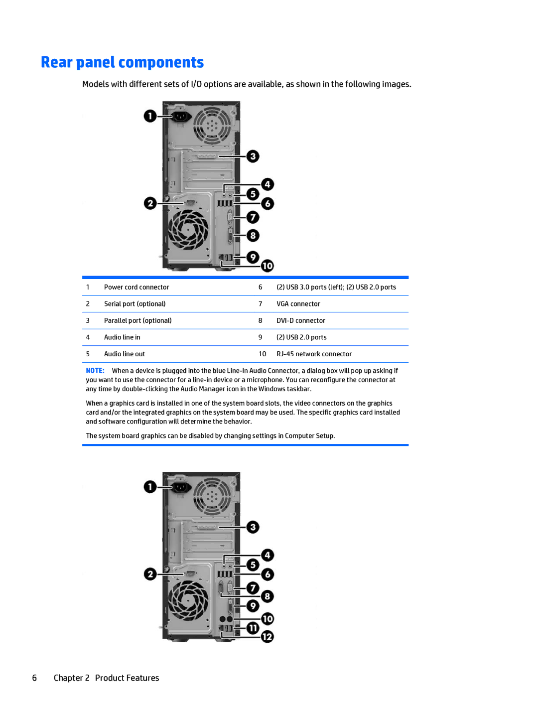
Rear panel components
Rear panel components
Serial Number Location
Computer major components
Illustrated parts catalog
Computer major components
Illustrated parts catalog
Access panel
Front I/O assembly
Item Description Front bezel
Misc parts
Wlan 802.11 a/b/g/n + Bluetooth 4.0 module
Misc parts
Graphics card, GeForce GT705 PCIe x16, 1 GB
Mouse
Drives
Item Description
Description Hard drives/Solid-state drives
Electrostatic discharge information
Electrostatic discharge information
Generating static
Relative Humidity Event 55% 40% 10%
Grounding the work area
Preventing electrostatic damage to equipment
Personal grounding methods and equipment
Static Shielding Protection Levels
Operating guidelines
Recommended materials and equipment
Cleaning the keyboard
General cleaning safety precautions
Cleaning the Computer Case
Routine care
Cleaning the mouse
Service considerations
Cleaning the monitor
Power supply fan
Screws
Cables and connectors
Lithium coin cell battery
Hard Drives
Sata hard drive cables
Serial ATA Hard Drive Characteristics
Sata hard drives
Smart ATA drives
Cable management
Removal and replacement procedures
Preparation for disassembly
Access panel
Front bezel
Optical drive bezel blank
DDR3/DDR3L-SDRAM UDIMMs
Memory
DIMMs
Populating Dimm sockets
Installing DIMMs
Expansion cards
Removal and replacement procedures
Page
Drives
Drive positions
Removing an optical drive
Removing a hard drive
Front I/O and power switch assembly
Page
Removal and replacement procedures
Card reader
Removal and replacement procedures
Heat sink
Processor
Speaker
Page
Page
Rear chassis fan
Page
Hood sensor
Power supply
Page
System board
System board callouts
Sys Bd Label Color Component
Computer Setup F10 Utility
Computer Setup F10 Utilities
Using Computer Setup F10 Utilities
Computer Setup-File
Computer Setup-Storage
Computer Setup F10 Utility
Computer Setup-Security
Device Security
Network Boot
Master Boot Security
USB Security
Legacy Support to disabled
Secure Boot
Configuration
System Security these
Option Description
Computer Setup-Power
Hardware Power
Management
Bios Power-On
Computer Setup-Advanced
Power-On Options
Option
Connected Bios
PCI VGA Configuration
Using the Dash Terminal Type option
Bus Options
Recovering the Configuration Settings
Troubleshooting without diagnostics
Safety and comfort Before you call for technical support
Helpful hints
Solving general problems
Computer will not respond to keyboard or mouse Cause
Solving general problems
Under Windows System, click Run
Poor performance Cause Solution
Apps icon
Processor thermal protection activated
Solving power problems
Power supply shuts down intermittently Cause Solution
Solving hard drive problems
Solving hard drive problems
Computer will not boot from hard drive Cause Solution
Nonsystem disk/NTLDR missing message Cause Solution
Storage Boot Order list
Storage Boot Order
Can not write to the media card Cause
Solving media card reader problems
Solving media card reader problems
Blank screen no video Cause Solution
Solving display problems
Inserted media card has boot capability
To the electrical outlet
Solving display problems
Blank screen no video Cause
Be sure the monitor cable is securely connected to
Dim characters Cause Solution
Install the video drivers included in the upgrade kit
Monitor needs to be degaussed
No Connection, Check Signal Cable displays on screen Cause
Image is not centered Cause Solution
Position may need adjustment
Horizontal or vertical position of the image
Sound cuts in and out Cause Solution
Solving audio problems
Certain typed symbols do not appear correct Cause
Solving audio problems
Line-in jack is not functioning properly Cause
Solving printer problems
Printer will not print Cause Solution
Control Panel , and then select Device Manager
Printer prints garbled information Cause Solution
Solving keyboard and mouse problems
Solving keyboard and mouse problems
Make the proper network connections to the printer
Shut down the computer using the keyboard
Keyboard connector is not properly connected
Program in use has stopped responding to commands
Computer, and then restart the computer
That pins in the connector are not bent down
Solving Hardware Installation Problems
Solving Hardware Installation Problems
Mouse may need repair
Computer will not start Cause Solution
Solving Network Problems
Solving Network Problems
Network status link light never flashes Cause Solution
Settings for the board
Correct operating mode
Diagnostics reports a failure Cause Solution
Cable Correctly
Solving memory problems
New network card will not boot Cause Solution
Memory count during Post is wrong Cause Solution
Solving memory problems
Out of memory error Cause
Insufficient memory error during operation Cause Solution
Security Network Boot
Solving CD-ROM and DVD problems
Computer Setup utility
Cannot eject compact disc tray-load unit Cause
Solving CD-ROM and DVD problems
Movie will not play in the DVD drive Cause Solution
System will not boot from USB flash drive Cause Solution
Solving USB flash drive problems
USB flash drive not found identified Cause Solution
Security USB Security
Solving front panel component problems
Solving front panel component problems
Solving Internet access problems
Log on to your ISP and launch the desired program
Solving software problems
Delete button
System files may be damaged
Select Automatic Repair
Solving software problems
Advanced startup, click Restart now
Post numeric codes and text messages
Post error messages
Post error messages
Control panel message Description Recommended action
Download to Disable to prevent PXE
Post numeric codes and text messages
Ensure that none of the keys are
Flash Screen Image Corrupted Flash Screen image has errors
ECC Memory Module Detected ECC
Depressed
Reconfigure card resources and/or run
Power Supply fan not detected
Reseat power supply fan
Computer Setup or Windows utilities
Functionality contained in the system Bios
Sata Cabling Error One or more Sata devices are improperly
Reboot the computer
System Bios version
Attached Enabled Turned off
Activity Beeps Possible cause Recommended action
Red Power LED flashes seven
Faulty module
Pre-video graphics error For systems with a graphics card
Times, once every second Unable to boot
Replace the power button harness. If
Open hood and check that the power button
Check that both power supply cables are
Problem persists, replace the system board
Password security and resetting Cmos
Resetting the Cmos and password jumper
Changing a Setup or Power-On password
Deleting a Setup or Power-On password
Press Enter Deleting a Setup or Power-On password
How to access and run HP PC Hardware Diagnostics
HP PC Hardware Diagnostics
Why run HP PC Hardware Diagnostics
Diagnostic section, click HP Uefi Support Environment
Restoring and recovering using Windows tools
System backup and recovery
Creating recovery media and backups
Using Reset when the system is not responding
Select Reset Follow the on-screen instructions to continue
Backing up, restoring, and recovering in Windows
Creating recovery media
Click All Programs
To create recovery discs Close all open programs
To create the Windows DVD System backup and recovery
System Restore
Follow the on-screen instructions to set up your backup
System Recovery
System Recovery when Windows is responding
System Recovery when Windows is not responding
Select Install now
Page
Battery replacement
Page
General Requirements
Power Cord Set Requirements
Japanese Power Cord Requirements
Country Accrediting Agency
Country-Specific Requirements
Country-Specific Requirements
Statement of Volatility
Appendix C Statement of Volatility
Enter the F10 setup utility
Appendix D Specifications
Specifications
Specifications
Recycling
125
Index
Illustrated Product description Audio Chipset Ethernet
Keyboard Cleaning Product description Keyboard problems
Memory module
Flash drive 112 System Recovery 114
108 Safety and comfort Safety precautions Cleaning
System restore points, creating
Processor Rear chassis fan Speaker