Manuals
/
HP
/
Computer Equipment
/
Laptop
HP
4311S
manual
Display assembly subcomponents
Models:
4311S
1
35
159
159
Download
159 pages
54.71 Kb
32
33
34
35
36
37
38
39
Specifications
Bluetooth
Pin Signal
Wireless
Maintenance
System Configuration menu
Access time
Computer Setup
Display assembly subcomponents
RTC battery
Page 35
Image 35
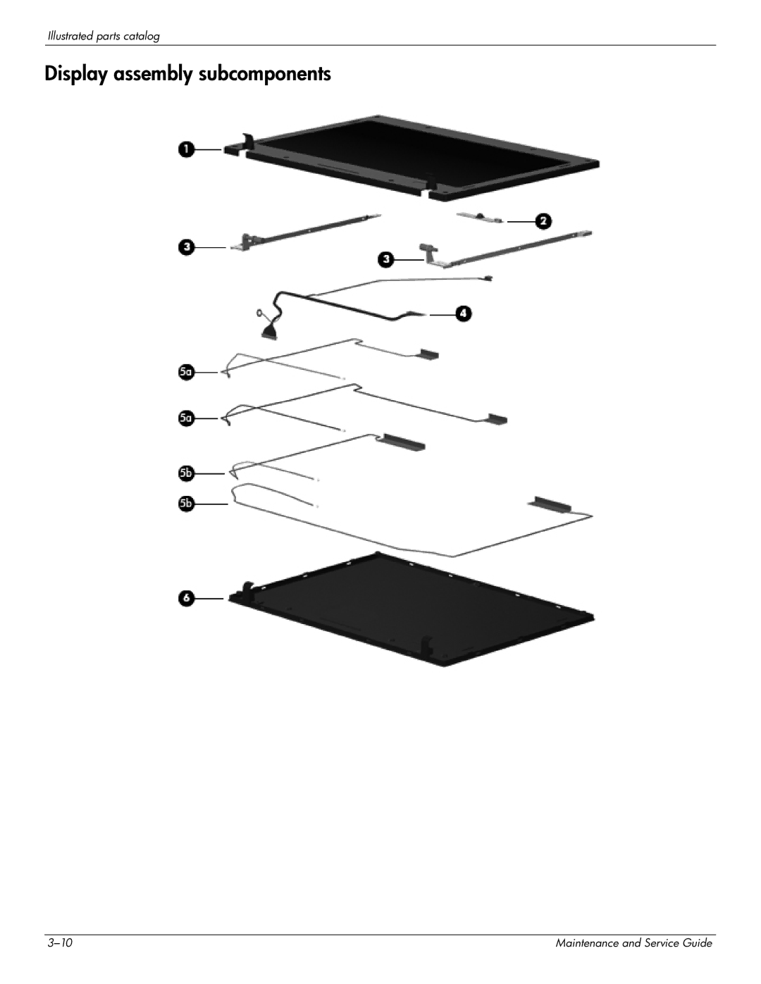
Illustrated parts catalog
Display assembly subcomponents
3–10
Maintenance and Service Guide
Page 34
Page 36
Page 35
Image 35
Page 34
Page 36
Contents
China only
Maintenance and Service Guide
Page
Safety warning notice
Contents
Removal and replacement procedures
Specifications
11Recycling
Processors
Product description
Category Description
Panel
GM45 chipset GL40 chipset Chipset
Graphics
GM45 chipset GL40 chipset Memory
Microphone
GM45 chipset GL40 chipset Hard drives
Optical drives
Diskette drive
Modem
Wireless
GM45 chipset GL40 chipset Audio
Webcam
Ports
Power
GM45 chipset GL40 chipset External media
Cards
Preinstalled with Microsoft Office
GM45 chipset GL40 chipset Operating system Preinstalled
Category Description
Component Description
External component identification
Display
Buttons and fingerprint reader
Top components
Windows XP Select Start Control Panel Performance
Maintenance Power Options
Windows Vista Select Start Control Panel System
Fn key
Keys
Component Description Esc key
Lights
Pointing devices
Front components
Right-side components
Left-side components
Bottom components
Illustrated parts catalog
Service tag
Computer major components
Item Description
Plastics Kit , includes
Bluetooth module
Modem module
RTC battery
Description Spare part number
Battery
Description Spare part number Wlan module
Description Spare part number Wlan module
Item Description Spare part number Cable Kit 577214-001
Cable Kit
Display assembly subcomponents
Display panel cable
Item Description Spare part number Display bezel
Webcam module
Display hinges
Item Description Spare part number Plastics Kit 577211-001
Plastics Kit
Item Description Spare part number
Mass storage devices
Screw Kit
Power cords
Miscellaneous parts
Description Spare part number AC adapters
Spare part number Description
Sequential part number listing
Spare part number Description
Module cable is included in the Cable Kit, spare part number
577181-001
Board and cable
Includes replacement thermal material
Tools required
Removal and replacement procedures
Preliminary replacement requirements
Service considerations
Drive handling
Grounding guidelines
Packaging and transporting guidelines
Material Use Voltage protection level
Workstation guidelines
Component replacement procedures
Computer feet
Battery
SIM
Hard drive
Removal and replacement procedures
Removal and replacement procedures
Wlan module
Description Spare part number
Removal and replacement procedures
Removal and replacement procedures
Memory module
Wwan module
Optical drive
Removal and replacement procedures
Keyboard for use in country Or region Spare part number
Keyboard and switch cover
Removal and replacement procedures
Removal and replacement procedures
Removal and replacement procedures
Speakers
Palm rest
Removal and replacement procedures
Display assembly
Removal and replacement procedures
Removal and replacement procedures
Removal and replacement procedures
Removal and replacement procedures
Removal and replacement procedures
Removal and replacement procedures
Removal and replacement procedures
Removal and replacement procedures
Top cover
Removal and replacement procedures
Removal and replacement procedures
USB board
Description Spare part number Bluetooth module
Bluetooth module
Removal and replacement procedures
Modem module
Removal and replacement procedures
Modem module cable
Power connector cable
Power button board spare part kit includes two cables
Power button board
System board
Removal and replacement procedures
Removal and replacement procedures
Network cable
Fan and heat sink
Removal and replacement procedures
Removal and replacement procedures
Description Spare part number RTC battery 581926-001
RTC battery
Processor
Removal and replacement procedures
Navigating and selecting in Computer Setup
Computer Setup
Starting Computer Setup
Using Computer Setup
Restoring factory settings in Computer Setup
Select To do this
Computer Setup menus
File menu
Security menu
System Configuration menu
Diagnostics menu
Select To do this System Configuration menu
Computer specifications
Specifications
Display specifications
Hard drive specifications
Cache buffer Data transfer rate
Access time
Applicable disc Read Write
CD-DA, CD+EG, CD-MIDI, CD-TEXT, CD-ROM, CD-ROM XA
Transfer mode
CD-TEXT, CD-ROM CD-ROM XA Mixed Mode CD, CD-I
DVD-ROM Drive specifications
Size Memory address System function
System DMA specifications
System memory map specifications
Hardware DMA System function
Hardware IRQ System function
System interrupt specifications
Address hex System function shipping configuration
System I/O address specifications
Ffff
Color Quantity Length Thread Head diameter Black
Screw listing
Phillips PM2.0×6.0 captive screw
Color Quantity Length Thread Head diameter Black 11.0 mm
Phillips PM2.5×11.0 captive screw
Color Quantity Length Thread Head diameter Silver
Phillips PM3.0×4.0 screw
Phillips PM2.5×4.0 screw
Phillips PM2.5×8.0 screw
Slotted Torx T8M2.5×7.0 screw
Screw listing
Torx T8M2.5×6.0 screw
Screw listing
Phillips PM2.0×4.0 screw
Screw listing
Phillips PM2.0×5.0 screw
Phillips PM2.0×2.0 broadhead screw
Phillips PM2.0×3.0 screw
Phillips PM2.0×9.0 captive screw
Screw listing
Overview
Backup and recovery
Backup and recovery in Windows Vista
Backing up your information
Using the Windows recovery tools
Performing a recovery
Using f11
Backup and recovery in Windows XP
Recovering your information
Audio-out headphone
Connector pin assignments
Pin Signal
Audio-in microphone
External monitor
Hdmi
RJ-11 modem
RJ-45 network
Universal Serial Bus
Requirements for all countries and regions
Power cord set requirements
Country/region Accredited agency Applicable note number
Requirements for specific countries and regions
Recycling
Battery
Recycling
Maintenance and Service Guide 11-3
11-4
Maintenance and Service Guide 11-5
11-6
Index
Index
Maintenance and Service Guide Index-3
Index-4
Maintenance and Service Guide Index-5
Index-6
Top
Page
Image
Contents