h.Display assembly (see Display assembly on page 59)
i.Top Cover (see Top cover on page 65)
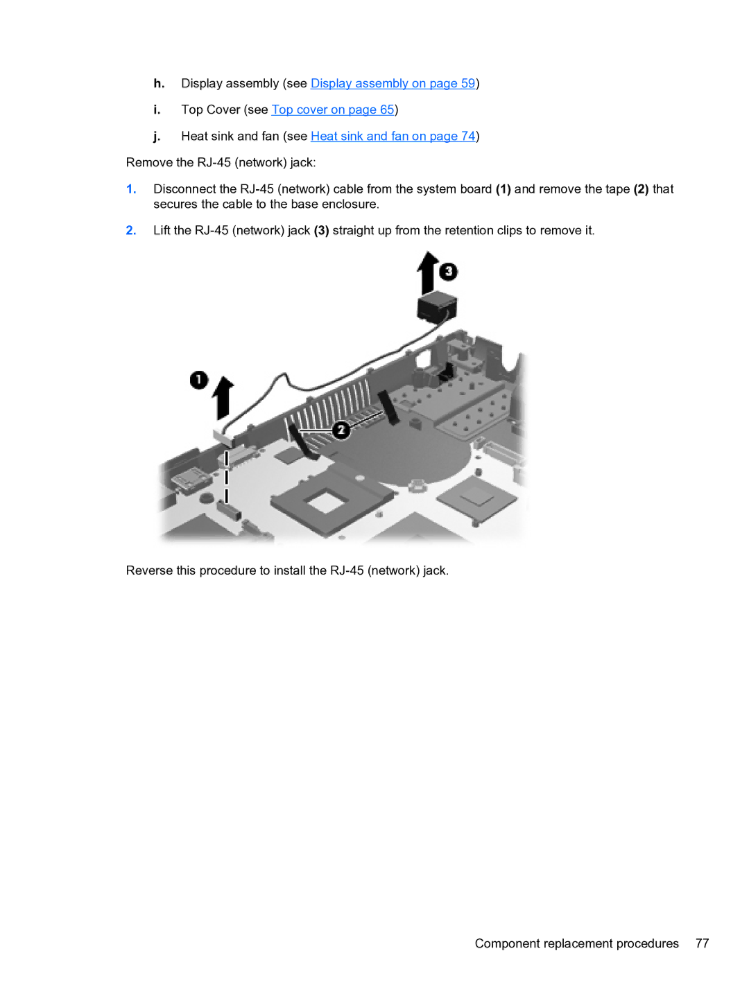
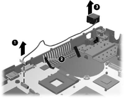
j.Heat sink and fan (see Heat sink and fan on page 74) Remove the
1.Disconnect the
2.Lift the
Reverse this procedure to install the
Component replacement procedures 77