4.Remove the battery (see Battery on page 41).
5.Remove the following components:
a.Switch cover and keyboard (see Switch cover and keyboard on page 42)
b.Memory module (see Memory module on page 45)
c.Optical drive (see Optical drive on page 47)
d.Speakers (see Speakers on page 49)
e.Palm rest (see Palm rest on page 50)
f.Hard drive (see Hard drive on page 52)
g.WLAN module (see WLAN module on page 55)
h.Display assembly (see Display assembly on page 59)
i.Top cover (see Top cover on page 65)
j.Heat sink and fan (see Heat sink and fan on page 74)
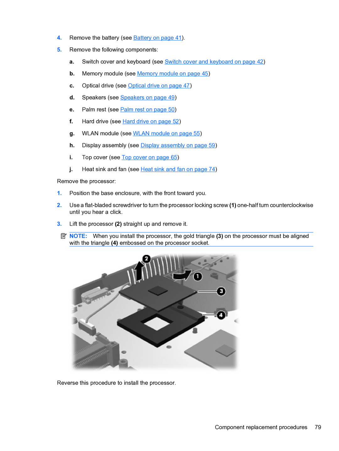
Remove the processor:
1.Position the base enclosure, with the front toward you.
2.Use a
3.Lift the processor (2) straight up and remove it.
![]() NOTE: When you install the processor, the gold triangle (3) on the processor must be aligned with the triangle (4) embossed on the processor socket.
NOTE: When you install the processor, the gold triangle (3) on the processor must be aligned with the triangle (4) embossed on the processor socket.
Reverse this procedure to install the processor.
Component replacement procedures 79