Removal and replacement procedures
✎Steps 5 through 21 provide display assembly internal component removal information for computer models equipped with AntiGlare display assemblies. See steps 22 through 38 for display assembly internal component removal information for computer models equipped with BrightView display assemblies.
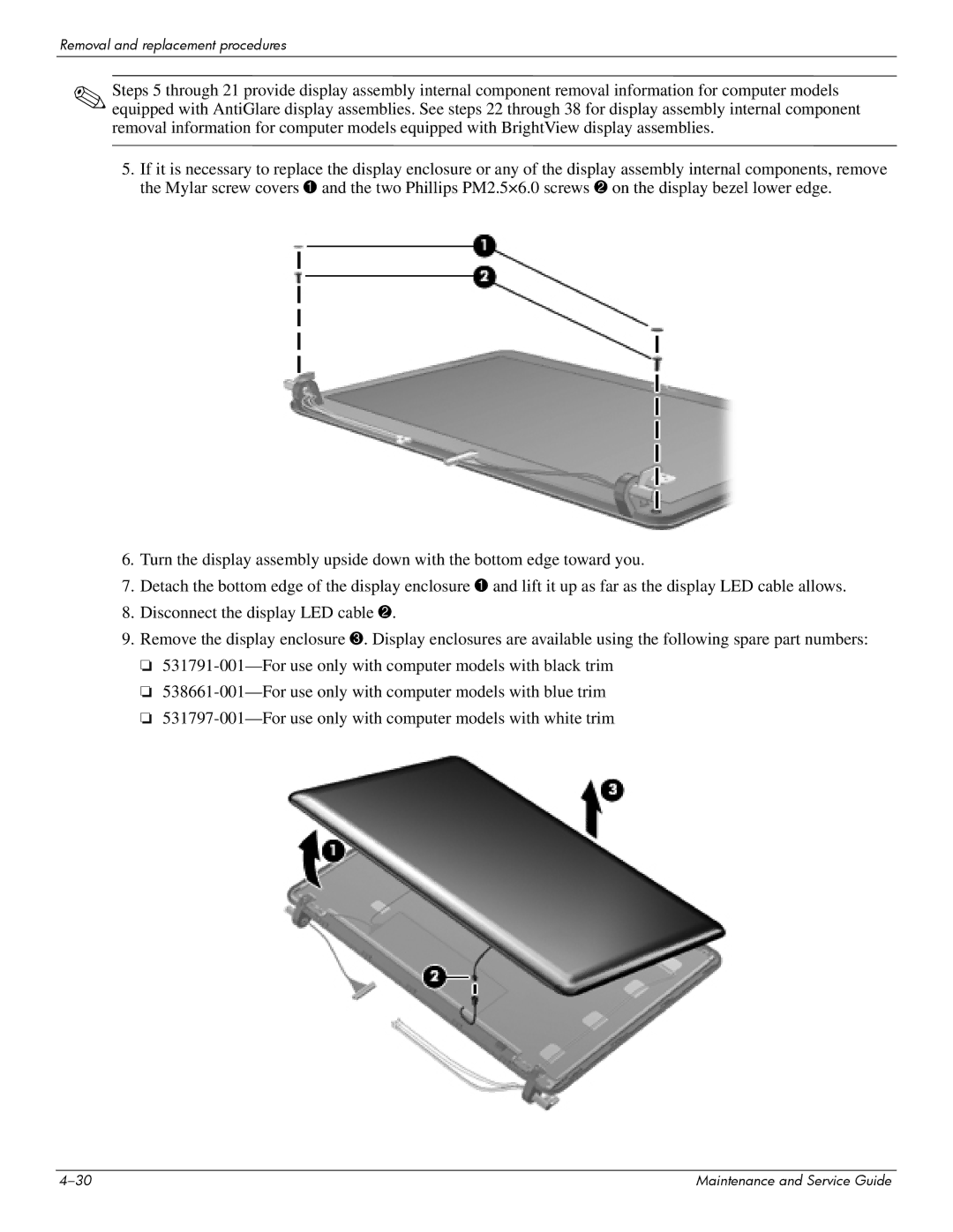
5.If it is necessary to replace the display enclosure or any of the display assembly internal components, remove the Mylar screw covers 1 and the two Phillips PM2.5×6.0 screws 2 on the display bezel lower edge.
6.Turn the display assembly upside down with the bottom edge toward you.
7.Detach the bottom edge of the display enclosure 1 and lift it up as far as the display LED cable allows.
8.Disconnect the display LED cable 2.
9.Remove the display enclosure 3. Display enclosures are available using the following spare part numbers:
❏
❏
❏
Maintenance and Service Guide |