Removal and replacement procedures
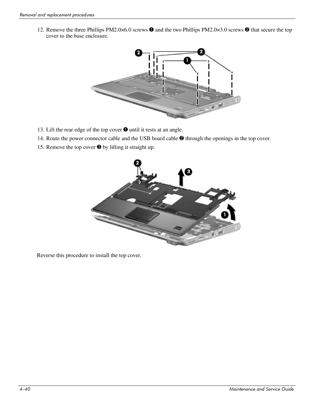
12.Remove the three Phillips PM2.0×6.0 screws 1 and the two Phillips PM2.0×3.0 screws 2 that secure the top cover to the base enclosure.
13.Lift the rear edge of the top cover 1 until it rests at an angle.
14.Route the power connector cable and the USB board cable 2 through the openings in the top cover.
15.Remove the top cover 3 by lifting it straight up.
Reverse this procedure to install the top cover.
Maintenance and Service Guide |
