Service and Error Messages
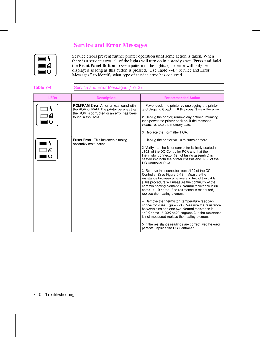
Service errors prevent further printer operation until some action is taken. When there is a service error, all of the lights will turn on in a steady state. Press and hold the Front Panel Button to see a pattern in the lights. (The error will only be displayed as long as this button is pressed.) Use Table
Table |
| Service and Error Messages (1 of 3) |
| |||
|
|
|
|
|
|
|
|
| LEDs |
| Description |
| Recommended Action |
|
|
|
|
|
|
|
|
|
| ROM/RAM Error. An error was found with |
| 1. | |
|
|
| the ROM or RAM. The printer believes that |
| and plugging it back in. If this doesn’t clear the error: | |
|
|
| the ROM is corrupted or an error has been |
|
| |
|
|
|
|
| ||
|
|
| found in the RAM. |
| 2. Unplug the printer, remove any optional memory, | |
|
|
|
| |||
|
|
|
| |||
|
|
|
|
|
| then power the printer back on. If the message |
|
|
|
|
|
| |
|
|
|
|
|
| clears, replace the memory card. |
|
|
|
|
|
| |
|
|
|
|
|
| 3. Replace the Formatter PCA. |
|
|
|
|
|
|
|
|
|
| Fuser Error. This indicates a fusing |
| 1. Unplug the printer for 10 minutes or more. | |
|
|
| assembly malfunction. |
| 2. Verify that the fuser connector is firmly seated in | |
|
|
|
| |||
|
|
|
|
|
| |
|
|
|
|
|
| J102 of the DC Controller PCA and that the |
|
|
|
|
|
| |
|
|
|
|
|
| |
|
|
|
|
|
| thermistor connector (left of fusing assembly) is |
|
|
|
|
|
| |
|
|
|
|
|
| seated into both the printer chassis and J206 of the |
|
|
|
|
|
| |
|
|
|
|
|
| DC Controller PCA. |
|
|
|
|
|
| 3. Remove the connector from J102 of the DC |
|
|
|
|
|
| Controller. (See Figure |
|
|
|
|
|
| resistance between pins one and two of the cable. |
|
|
|
|
|
| (This procedure will measure the continuity of the |
|
|
|
|
|
| ceramic heating element.) Normal resistance is 30 |
|
|
|
|
|
| ohms +/- 10 ohms. If no resistance is measured, |
|
|
|
|
|
| replace the heating element. |
|
|
|
|
|
| 4. Remove the thermistor (temperature feedback) |
|
|
|
|
|
| connector. (See Figure |
|
|
|
|
|
| between pins one and two. Normal resistance is |
|
|
|
|
|
| 440K ohms +/- 30K at 20 degrees C. If the resistance |
|
|
|
|
|
| is not measured replace the heating element. |
|
|
|
|
|
| 5. If the resistance readings are correct, yet the error |
|
|
|
|
|
| persists, replace the DC Controller. |
|
|
|
|
|
|
|