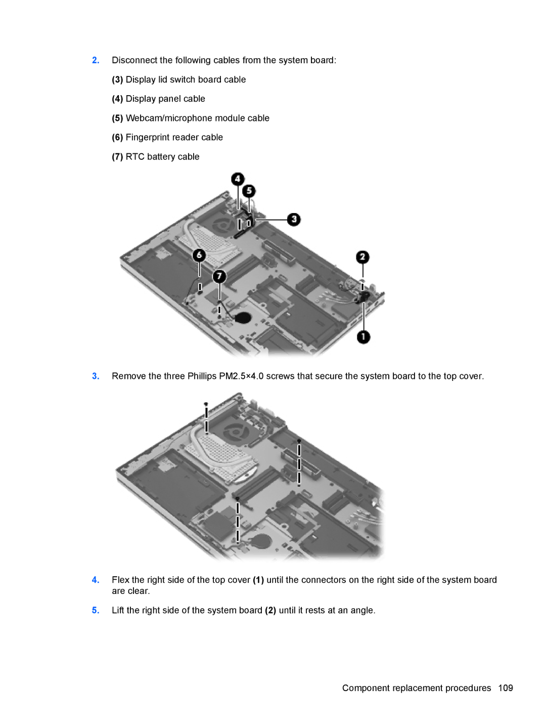
2.Disconnect the following cables from the system board:
(3)Display lid switch board cable
(4)Display panel cable
(5)Webcam/microphone module cable
(6)Fingerprint reader cable
(7)RTC battery cable
3.Remove the three Phillips PM2.5×4.0 screws that secure the system board to the top cover.
4.Flex the right side of the top cover (1) until the connectors on the right side of the system board are clear.
5.Lift the right side of the system board (2) until it rests at an angle.
