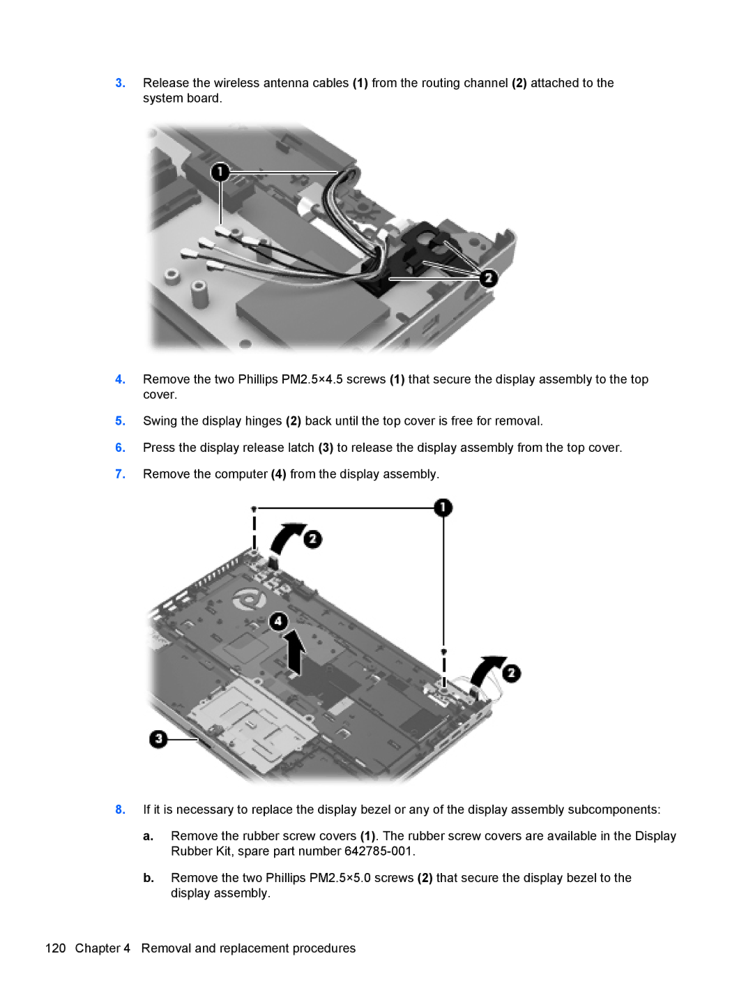
3.Release the wireless antenna cables (1) from the routing channel (2) attached to the system board.
4.Remove the two Phillips PM2.5×4.5 screws (1) that secure the display assembly to the top cover.
5.Swing the display hinges (2) back until the top cover is free for removal.
6.Press the display release latch (3) to release the display assembly from the top cover.
7.Remove the computer (4) from the display assembly.
8.If it is necessary to replace the display bezel or any of the display assembly subcomponents:
a.Remove the rubber screw covers (1). The rubber screw covers are available in the Display Rubber Kit, spare part number
b.Remove the two Phillips PM2.5×5.0 screws (2) that secure the display bezel to the display assembly.
120 Chapter 4 Removal and replacement procedures
