2.9Connectors Pin Assignments
2.9.1Pin Assignments of PCI-9112
The
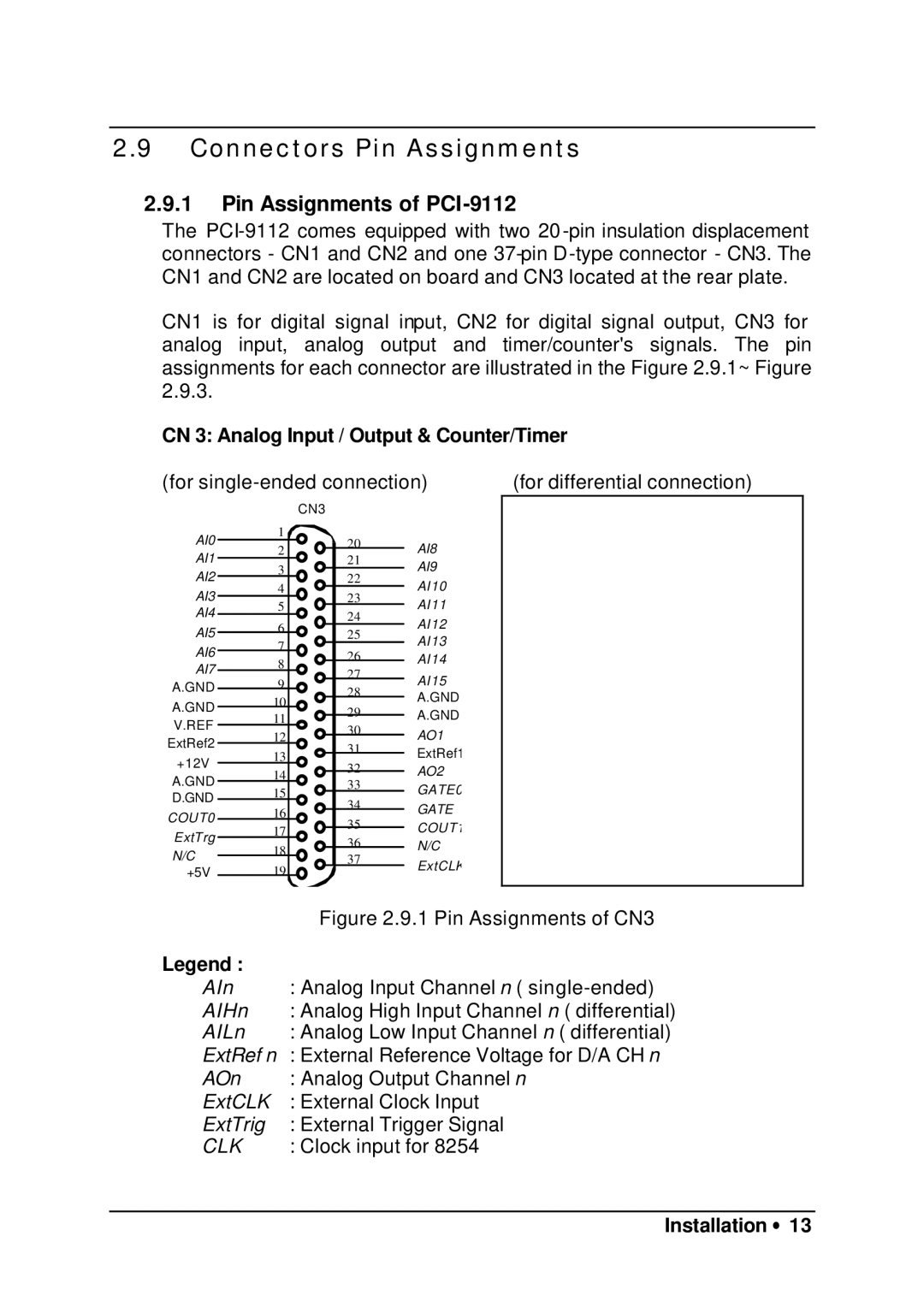
CN1 is for digital signal input, CN2 for digital signal output, CN3 for analog input, analog output and timer/counter's signals. The pin assignments for each connector are illustrated in the Figure 2.9.1~ Figure 2.9.3.
CN 3: Analog Input / Output & Counter/Timer
(for | (for differential connection) | |||||||||
|
|
|
| CN3耟 |
|
|
| |||
AI0 | 耟 | 1耟 |
|
| 20耟 |
|
|
| ||
2耟 |
|
| AI8 耟 |
|
| |||||
AI1 | 耟 |
|
| 21耟 |
|
| ||||
3耟 |
|
| AI9 耟 |
|
| |||||
AI2 | 耟 |
|
| 22耟 |
|
| ||||
4耟 |
|
| AI10耟 |
|
| |||||
AI3 | 耟 |
|
| 23耟 |
|
| ||||
5耟 |
|
| AI11耟 |
|
| |||||
AI4 | 耟 |
|
| 24耟 |
|
| ||||
6耟 |
|
| AI12耟 |
|
| |||||
AI5 | 耟 |
|
| 25耟 |
|
| ||||
7耟 |
|
|
| AI13耟 |
|
| ||||
AI6 | 耟 |
|
|
| 26耟 |
|
| |||
8耟 |
|
| AI14耟 |
|
| |||||
AI7 | 耟 |
|
| 27耟 |
|
| ||||
9耟 |
|
|
| AI15耟 |
|
| ||||
A.GND | 耟 |
|
|
| 28耟 |
|
| |||
|
|
| A.GND耟 |
|
| |||||
A.GND | 耟 | 10 | 耟 |
|
| 29耟 |
|
| ||
11 耟 |
|
| A.GND耟 |
|
| |||||
V.REF耟 |
|
|
|
| ||||||
12 | 耟 |
|
| 30耟 | AO1 耟 |
|
| |||
ExtRef2 | 耟 |
|
| 31耟 |
|
| ||||
13 | 耟 |
|
| ExtRef1 |
|
| ||||
+12V耟 |
|
| 32耟 |
|
| |||||
14 耟 |
|
| AO2 耟 |
|
| |||||
A.GND | 耟 |
|
|
|
| |||||
15 耟 |
|
| 33耟 | GATE0 |
|
| ||||
D.GND | 耟 |
|
|
|
| |||||
16 | 耟 |
|
| 34耟 | GATE 耟 |
|
| |||
COUT0耟 |
|
|
|
| ||||||
|
| 35耟 |
|
| ||||||
17 | 耟 |
|
| COUT1 |
|
| ||||
ExtTrg耟 |
|
|
|
| ||||||
18 | 耟 |
|
| 36耟 | N/C耟 |
|
| |||
N/C耟 |
|
|
|
|
| |||||
|
|
| 37耟 |
| ||||||
| 19 |
|
|
|
| ExtCLK |
|
| ||
+5V 耟 | 耟 |
|
|
|
|
| ||||
|
|
|
|
|
| |||||
|
|
|
|
|
|
| ||||
|
|
|
|
|
|
| ||||
|
|
|
|
| Figure 2.9.1 Pin Assignments of CN3 | |||||
Legend : |
|
|
|
|
|
|
|
|
| |
AIn |
| : Analog Input Channel n ( | ||||||||
AIHn |
| : Analog High Input Channel n ( differential) | ||||||||
AILn |
| : Analog Low Input Channel n ( differential) | ||||||||
ExtRef n : External Reference Voltage for D/A CH n | ||||||||||
AOn |
| : Analog Output Channel n | ||||||||
ExtCLK |
| : External Clock Input |
| |||||||
ExtTrig |
| : External Trigger Signal |
| |||||||
CLK |
| : Clock input for 8254 |
| |||||||