4. Remove the two Phillips PM2.5×9.0 screws (2) that secure the display bezel bottom edge to the display assembly.
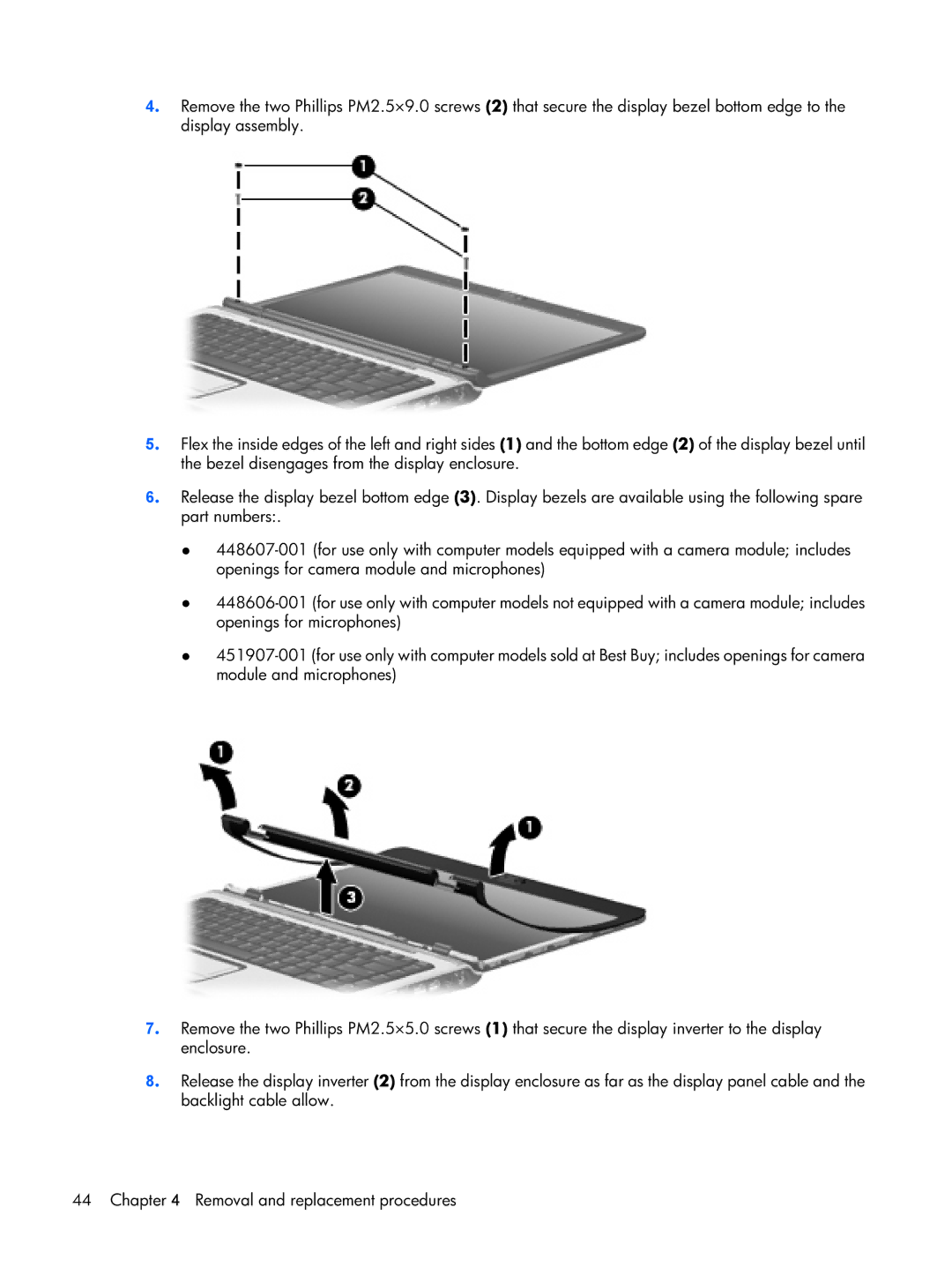
5. Flex the inside edges of the left and right sides (1) and the bottom edge (2) of the display bezel until the bezel disengages from the display enclosure.
6. Release the display bezel bottom edge (3). Display bezels are available using the following spare part numbers:.
●
●
●
7. Remove the two Phillips PM2.5×5.0 screws (1) that secure the display inverter to the display enclosure.
8. Release the display inverter (2) from the display enclosure as far as the display panel cable and the backlight cable allow.
44 Chapter 4 Removal and replacement procedures