6. Release the display bezel top edge (3). Display bezels are available using the following spare part numbers:
●
●
●
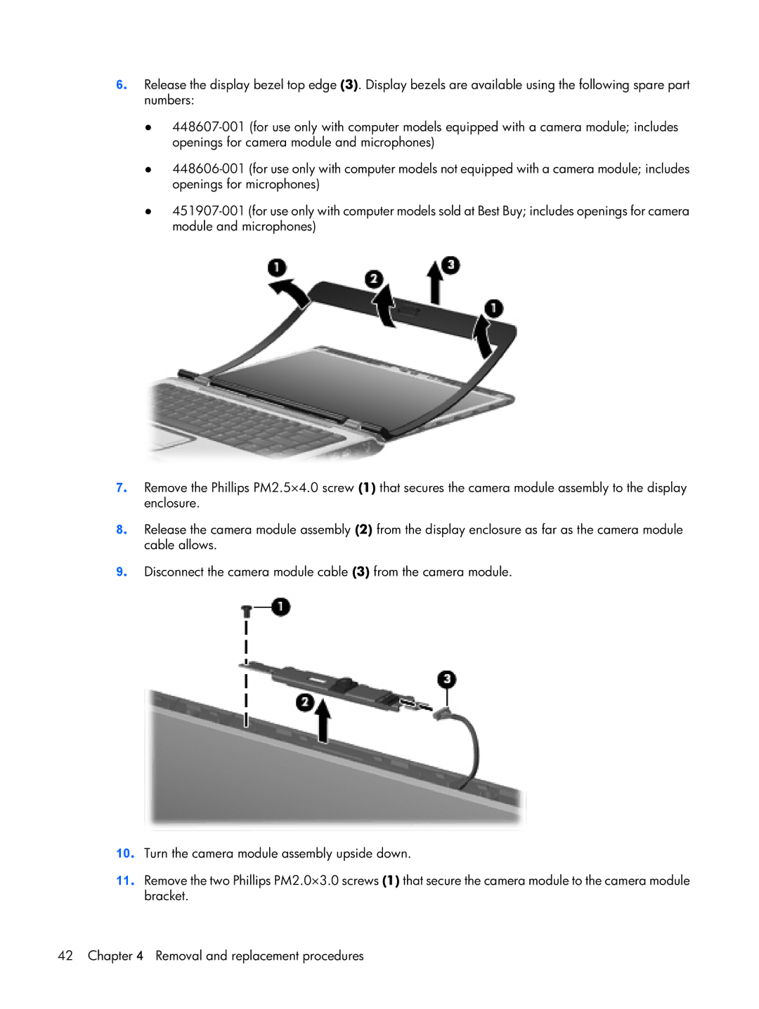
7. Remove the Phillips PM2.5×4.0 screw (1) that secures the camera module assembly to the display enclosure.
8. Release the camera module assembly (2) from the display enclosure as far as the camera module cable allows.
9. Disconnect the camera module cable (3) from the camera module.
10. Turn the camera module assembly upside down.
11. Remove the two Phillips PM2.0×3.0 screws (1) that secure the camera module to the camera module bracket.
42 Chapter 4 Removal and replacement procedures