f.Display assembly (see Display assembly on page 63)
g.System board (see System board on page 70) Remove the heat sink:
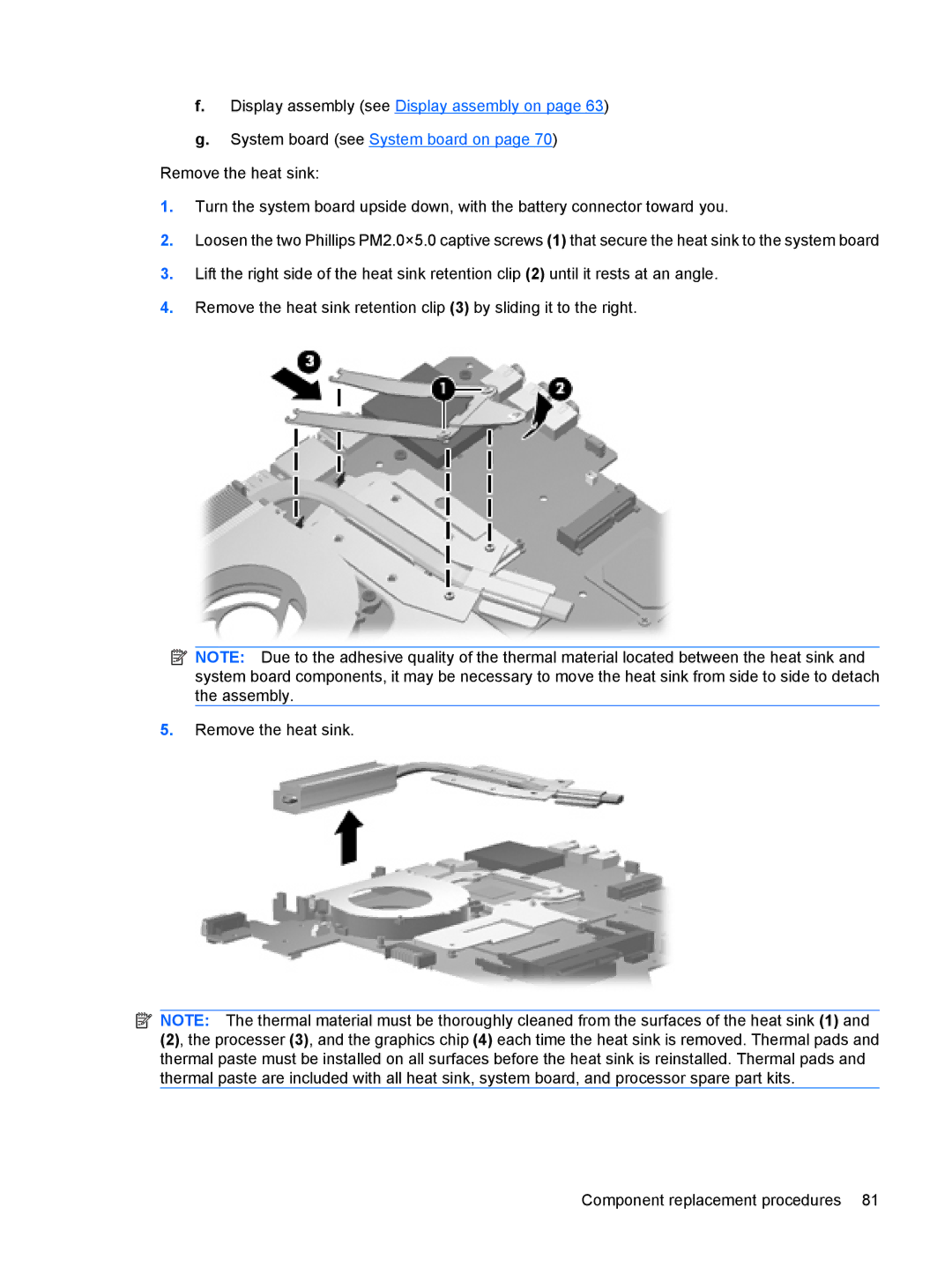
1.Turn the system board upside down, with the battery connector toward you.
2.Loosen the two Phillips PM2.0×5.0 captive screws (1) that secure the heat sink to the system board
3.Lift the right side of the heat sink retention clip (2) until it rests at an angle.
4.Remove the heat sink retention clip (3) by sliding it to the right.
![]() NOTE: Due to the adhesive quality of the thermal material located between the heat sink and system board components, it may be necessary to move the heat sink from side to side to detach the assembly.
NOTE: Due to the adhesive quality of the thermal material located between the heat sink and system board components, it may be necessary to move the heat sink from side to side to detach the assembly.
5.Remove the heat sink.
![]() NOTE: The thermal material must be thoroughly cleaned from the surfaces of the heat sink (1) and
NOTE: The thermal material must be thoroughly cleaned from the surfaces of the heat sink (1) and
(2), the processer (3), and the graphics chip (4) each time the heat sink is removed. Thermal pads and thermal paste must be installed on all surfaces before the heat sink is reinstalled. Thermal pads and thermal paste are included with all heat sink, system board, and processor spare part kits.
Component replacement procedures 81