4.Remove the WLAN antenna cables from the channel (2) located between the wireless module compartment and the memory module compartment.
5.Turn the computer
6.Open the computer as far as possible.
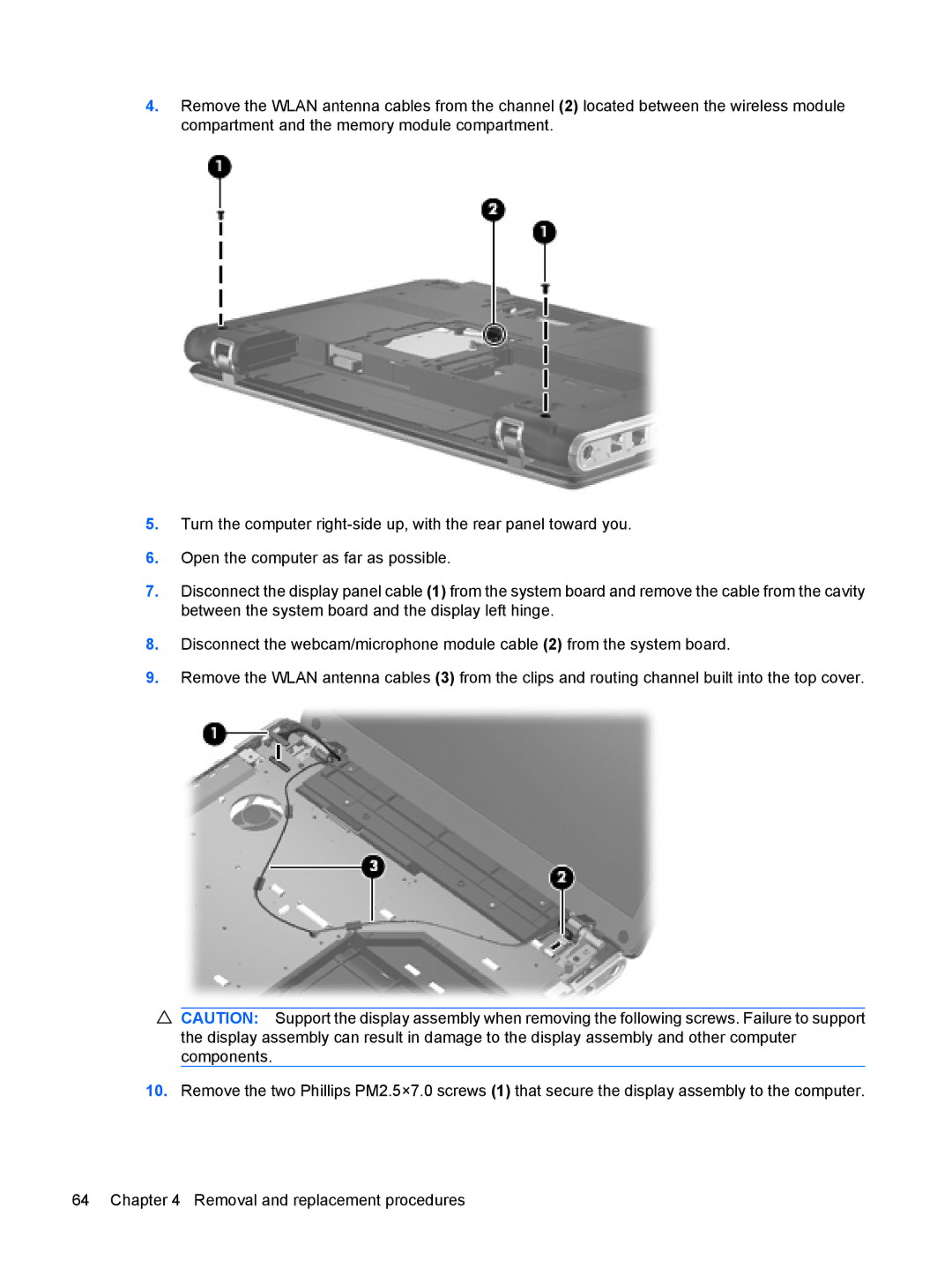
7.Disconnect the display panel cable (1) from the system board and remove the cable from the cavity between the system board and the display left hinge.
8.Disconnect the webcam/microphone module cable (2) from the system board.
9.Remove the WLAN antenna cables (3) from the clips and routing channel built into the top cover.
CAUTION: Support the display assembly when removing the following screws. Failure to support the display assembly can result in damage to the display assembly and other computer components.
10.Remove the two Phillips PM2.5×7.0 screws (1) that secure the display assembly to the computer.
64 Chapter 4 Removal and replacement procedures