e.Hard drive (see Hard drive on page 78)
f.Display assembly (see Display assembly on computers with
g.Top cover (see Top cover on page 90)
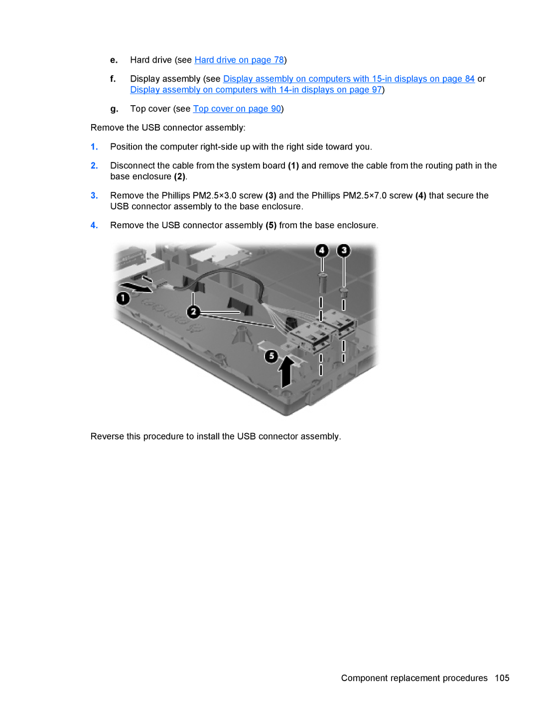
Remove the USB connector assembly:
1.Position the computer
2.Disconnect the cable from the system board (1) and remove the cable from the routing path in the base enclosure (2).
3.Remove the Phillips PM2.5×3.0 screw (3) and the Phillips PM2.5×7.0 screw (4) that secure the USB connector assembly to the base enclosure.
4.Remove the USB connector assembly (5) from the base enclosure.
Reverse this procedure to install the USB connector assembly.
Component replacement procedures 105
