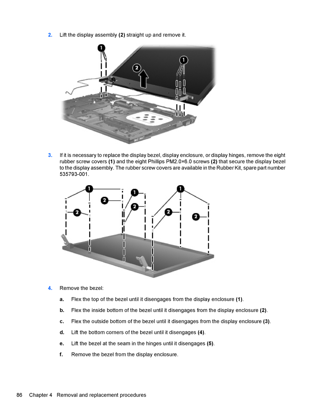
2.Lift the display assembly (2) straight up and remove it.
3.If it is necessary to replace the display bezel, display enclosure, or display hinges, remove the eight rubber screw covers (1) and the eight Phillips PM2.0×6.0 screws (2) that secure the display bezel to the display assembly. The rubber screw covers are available in the Rubber Kit, spare part number
4.Remove the bezel:
a.Flex the top of the bezel until it disengages from the display enclosure (1).
b.Flex the inside bottom of the bezel until it disengages from the display enclosure (2).
c.Flex the outside bottom of the bezel until it disengages from the display enclosure (3).
d.Lift the bottom corners of the bezel until it disengages (4).
e.Lift the bezel at the seam in the hinges until it disengages (5).
f.Remove the bezel from the display enclosure.
86 Chapter 4 Removal and replacement procedures