Removal and Replacement Procedures
5.2 Disassembly Sequence Chart
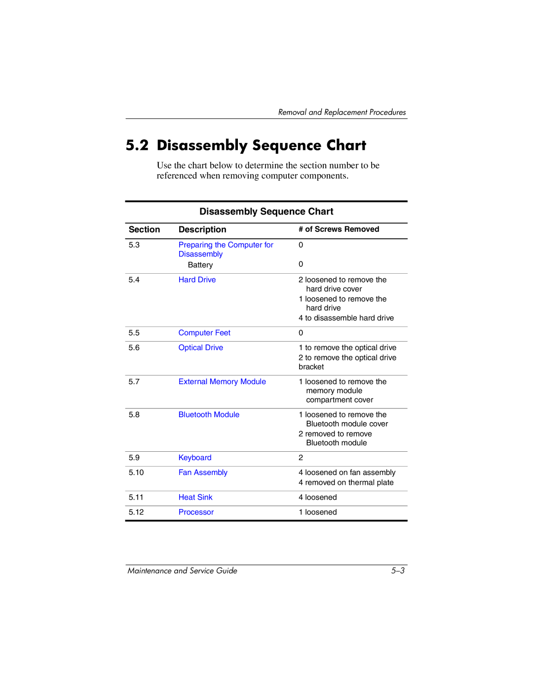
Use the chart below to determine the section number to be referenced when removing computer components.
Disassembly Sequence Chart
Section | Description | # of Screws Removed |
|
|
|
5.3 | Preparing the Computer for | 0 |
| Disassembly |
|
| Battery | 0 |
|
|
|
5.4 | Hard Drive | 2 loosened to remove the |
|
| hard drive cover |
|
| 1 loosened to remove the |
|
| hard drive |
|
| 4 to disassemble hard drive |
|
|
|
5.5 | Computer Feet | 0 |
|
|
|
5.6 | Optical Drive | 1 to remove the optical drive |
|
| 2 to remove the optical drive |
|
| bracket |
|
|
|
5.7 | External Memory Module | 1 loosened to remove the |
|
| memory module |
|
| compartment cover |
|
|
|
5.8 | Bluetooth Module | 1 loosened to remove the |
|
| Bluetooth module cover |
|
| 2 removed to remove |
|
| Bluetooth module |
|
|
|
5.9 | Keyboard | 2 |
|
|
|
5.10 | Fan Assembly | 4 loosened on fan assembly |
|
| 4 removed on thermal plate |
|
|
|
5.11 | Heat Sink | 4 loosened |
|
|
|
5.12 | Processor | 1 loosened |
|
|
|
Maintenance and Service Guide |