Fan/heat sink assembly
Description | Spare part number |
|
|
Fan/heat sink assembly (includes replacement thermal material) | |
|
|
Before removing the fan/heat sink assembly, follow these steps:
1.Turn off the computer. If you are unsure whether the computer is off or in Hibernation, turn the computer on, and then shut it down through the operating system.
2.Disconnect the power from the computer by unplugging the power cord from the computer.
3.Disconnect all external devices from the computer.
4.Remove the battery (see Battery on page 28), and then remove the following components:
a.Service door (see Service door on page 30)
b.Keyboard (see Keyboard on page 41)
c.Top cover (see Top cover on page 45)
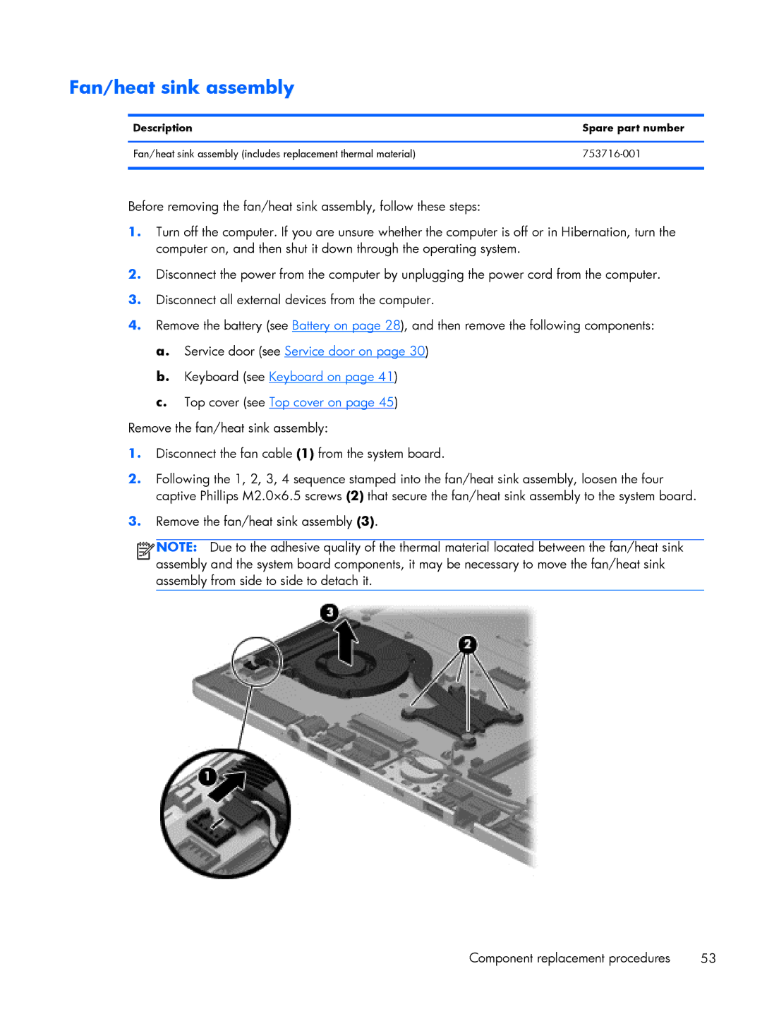
Remove the fan/heat sink assembly:
1.Disconnect the fan cable (1) from the system board.
2.Following the 1, 2, 3, 4 sequence stamped into the fan/heat sink assembly, loosen the four captive Phillips M2.0×6.5 screws (2) that secure the fan/heat sink assembly to the system board.
3.Remove the fan/heat sink assembly (3).
![]()
![]()
![]()
![]() NOTE: Due to the adhesive quality of the thermal material located between the fan/heat sink
NOTE: Due to the adhesive quality of the thermal material located between the fan/heat sink
assembly and the system board components, it may be necessary to move the fan/heat sink assembly from side to side to detach it.
Component replacement procedures | 53 |