ELECTRICAL SYSTEM
Relays
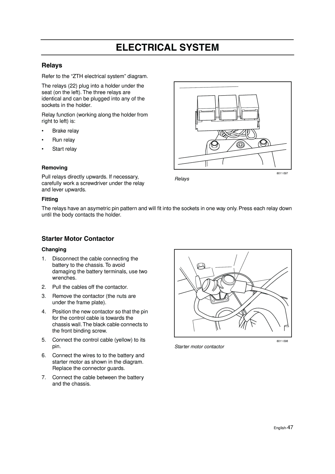
Refer to the “ZTH electrical system” diagram.
The relays (22) plug into a holder under the seat (on the left). The three relays are identical and can be plugged into any of the sockets in the holder.
Relay function (working along the holder from right to left) is:
• | Brake relay |
| |
• | Run relay |
| |
• | Start relay |
| |
Removing |
| ||
Pull relays directly upwards. If necessary, | |||
Relays | |||
carefully work a screwdriver under the relay | |||
| |||
and lever upwards. |
| ||
Fitting
The relays have an asymetric pin pattern and will fit into the sockets in one way only. Press each relay down until the body contacts the holder.
Starter Motor Contactor
Changing
1.Disconnect the cable connecting the battery to the chassis. To avoid damaging the battery terminals, use two wrenches.
2.Pull the cables off the contactor.
3.Remove the contactor (the nuts are under the frame plate).
4.Position the new contactor so that the pin for the control cable is towards the chassis wall. The black cable connects to the front binding screw.
5.Connect the control cable (yellow) to its pin.
6.Connect the wires to to the battery and starter motor as shown in the diagram. Replace the connector guards.
7.Connect the cable between the battery and the chassis.
Starter motor contactor