DESIGN AND FUNCTION
Engine
Husqvarna’s
Major engine repairs are not covered in this workshop manual. Users are referred to Kawasaki’s own manuals. These contain detailed information on the adjustment and repair of the engines. The manuals can be ordered from authorized service workshops.
The table below shows the information to be quoted when ordering engine manuals:
Model | Kawasaki’s | Power | Publication | |
engine type | Kawasaki no. | |||
|
| |||
|
|
|
| |
ZTH5223 | 17.5 kW (23 hp) | |||
ZTH6125 | 18.6 kW (25 hp) | |||
|
|
|
|
When repairing engines, use genuine spare parts only. The warranty will be invalidated if other parts are used.
Drive and Control
Via a belt, the engine supplies direct, clutchles, drive to two hydraulic pumps. The pumps have axial pistons.
Each pump feeds oil to a fixed
Hydrostatic braking occurs whenever there is no flow of oil from the pumps.
Instructions for the repair of the hydraulic pumps are given in the
Brakes
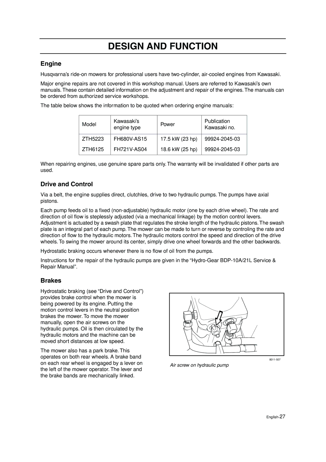
Hydrostatic braking (see “Drive and Control”) provides brake control when the mower is being powered by its engine. Putting the motion control levers in the neutral position brakes the mower. To move the mower manually, open the air screws on the hydraulic pumps. Oil is then circulated by the hydraulic motors and the machine can be moved short distances at low speed.
The mower also has a park brake. This operates on both rear wheels. A brake band
on each rear wheel is engaged by a lever on | Air screw on hydraulic pump | |
the left of the mower operator. The lever and | ||
| ||
the brake bands are mechanically linked. |
|