ELECTRICAL SYSTEM
Electrical System
Troubleshooting
See the “Troubleshooting” section towards the back of this manual.
Wiring Assembly
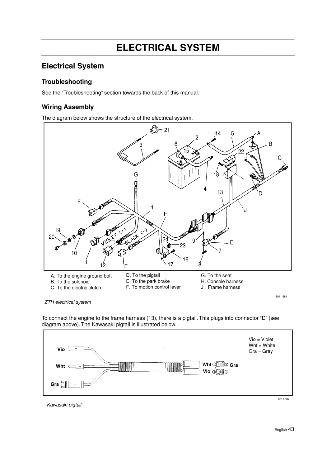
The diagram below shows the structure of the electrical system.
A. To the engine ground bolt B. To the solenoid
C. To the electric clutch
D. To the pigtail | G. To the seat |
E. To the park brake | H. Console harness |
F. To motion control lever | J. Frame harness |
ZTH electrical system
To connect the engine to the frame harness (13), there is a pigtail. This plugs into connector “D” (see diagram above). The Kawasaki pigtail is illustrated below.
Vio = Violet
Wht = White
Gra = Gray
Kawasaki pigtail
