Chapter 4
o e
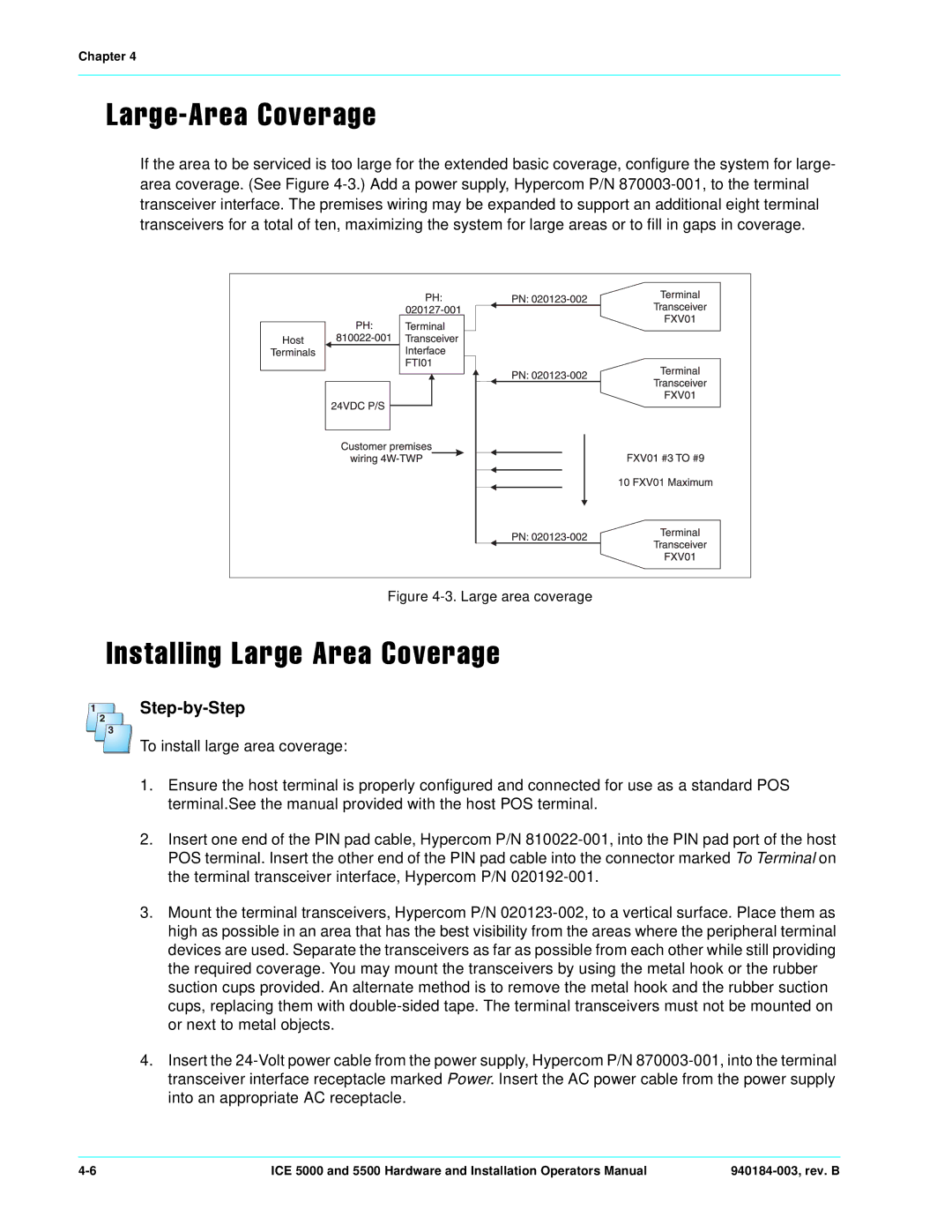
If the area to be serviced is too large for the extended basic coverage, configure the system for large- area coverage. (See Figure 4-3.) Add a power supply, Hypercom P/N 870003-001, to the terminal transceiver interface. The premises wiring may be expanded to support an additional eight terminal transceivers for a total of ten, maximizing the system for large areas or to fill in gaps in coverage.
Figure 4-3. Large area coverage
l e
Step-by-Step
To install large area coverage:
1.Ensure the host terminal is properly configured and connected for use as a standard POS terminal.See the manual provided with the host POS terminal.
2.Insert one end of the PIN pad cable, Hypercom P/N 810022-001, into the PIN pad port of the host POS terminal. Insert the other end of the PIN pad cable into the connector marked To Terminal on the terminal transceiver interface, Hypercom P/N 020192-001.
3.Mount the terminal transceivers, Hypercom P/N 020123-002, to a vertical surface. Place them as high as possible in an area that has the best visibility from the areas where the peripheral terminal devices are used. Separate the transceivers as far as possible from each other while still providing the required coverage. You may mount the transceivers by using the metal hook or the rubber suction cups provided. An alternate method is to remove the metal hook and the rubber suction cups, replacing them with double-sided tape. The terminal transceivers must not be mounted on or next to metal objects.
4.Insert the 24-Volt power cable from the power supply, Hypercom P/N 870003-001, into the terminal transceiver interface receptacle marked Power. Insert the AC power cable from the power supply into an appropriate AC receptacle.
4-6 | ICE 5000 and 5500 Hardware and Installation Operators Manual | 940184-003, rev. B |