EM78M611E
Universal Serial Bus Series Microcontroller
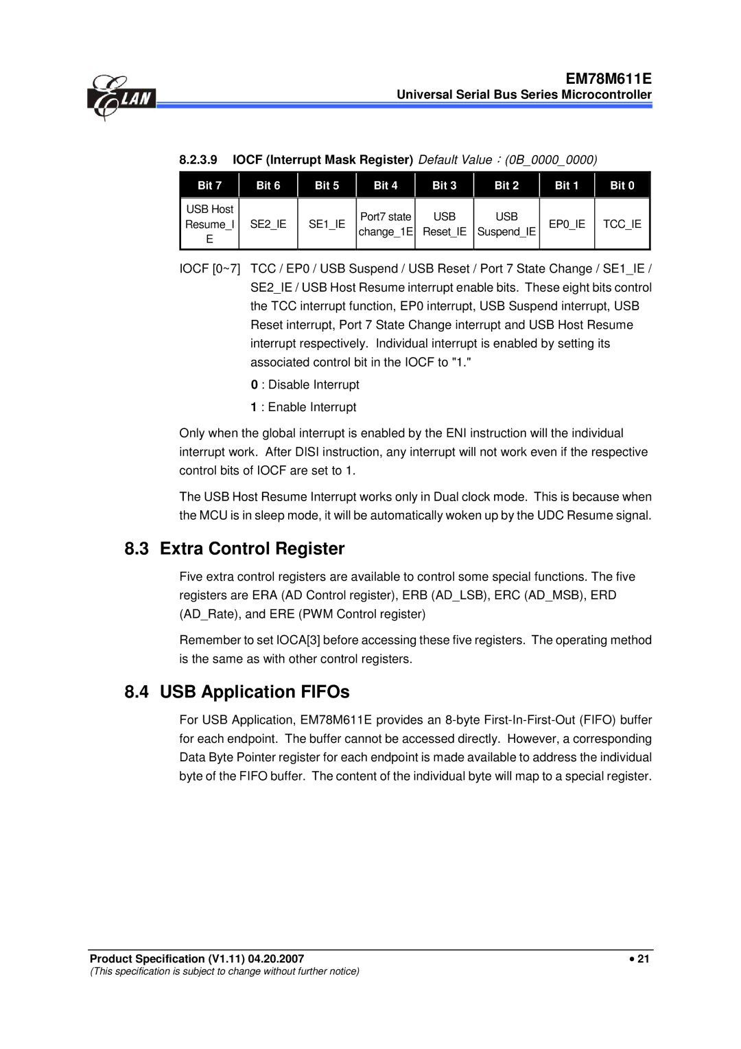
8.2.3.9 IOCF (Interrupt Mask Register) Default Value (0B_0000_0000)
Bit 7 |
| Bit 6 |
| Bit 5 |
| Bit 4 |
| Bit 3 |
| Bit 2 |
| Bit 1 |
| Bit 0 |
|
|
|
|
|
|
|
|
|
|
|
|
|
|
|
USB Host |
|
|
|
|
| Port7 state |
| USB |
| USB |
|
|
|
|
Resume_I |
| SE2_IE |
| SE1_IE |
|
|
|
| EP0_IE |
| TCC_IE | |||
|
|
| change_1E |
| Reset_IE |
| Suspend_IE |
|
| |||||
E |
|
|
|
|
|
|
|
|
|
|
| |||
|
|
|
|
|
|
|
|
|
|
|
|
|
| |
|
|
|
|
|
|
|
|
|
|
|
|
|
|
|
IOCF [0~7] TCC / EP0 / USB Suspend / USB Reset / Port 7 State Change / SE1_IE / | ||||||||||||||
|
| SE2_IE / USB Host Resume interrupt enable bits. These eight bits control | ||||||||||||
|
| the TCC interrupt function, EP0 interrupt, USBJSuspend interrupt, USB | ||||||||||||
|
| Reset interrupt, Port 7 State Change interrupt and USB Host Resume | ||||||||||||
|
| interrupt respectively. Individual interrupt is enabled by setting its | ||||||||||||
|
| associated control bit in the IOCF to "1." |
|
|
|
|
|
| ||||||
0 : Disable Interrupt
1 : Enable Interrupt
Only when the global interrupt is enabled by the ENI instruction will the individual interrupt work. After DISI instruction, any interrupt will not work even if the respective control bits of IOCF are set to 1.
The USB Host Resume Interrupt works only in Dual clock mode. This is because when the MCU is in sleep mode, it will be automatically woken up by the UDC Resume signal.
8.3 Extra Control Register
Five extra control registers are available to control some special functions. The five registers are ERA (AD Control register), ERB (AD_LSB), ERC (AD_MSB), ERD (AD_Rate), and ERE (PWM Control register)
Remember to set IOCA[3] before accessing these five registers. The operating method is the same as with other control registers.
8.4 USB Application FIFOs
For USB Application, EM78M611E provides an
Product Specification (V1.11) 04.20.2007 | • 21 |
(This specification is subject to change without further notice)