EM78M611E
Universal Serial Bus Series Microcontroller
8.2.2.11RA (EEPROM Control Register) Default Value: (0B_1111_1111)
RA is a command register for EEPROM control. For detailed usage of this register, refer to Section 8.2.3 which describes the EEPROM embedded in the EM78M611E.
8.2.2.12RB (Pattern Detect Application Control Register) Default Value: (0B_0000_0000)
RB is a control register for controlling the Pattern Detect Application function. For detailed description of this register, refer to Section 8.7.2 which describes the PDA function.
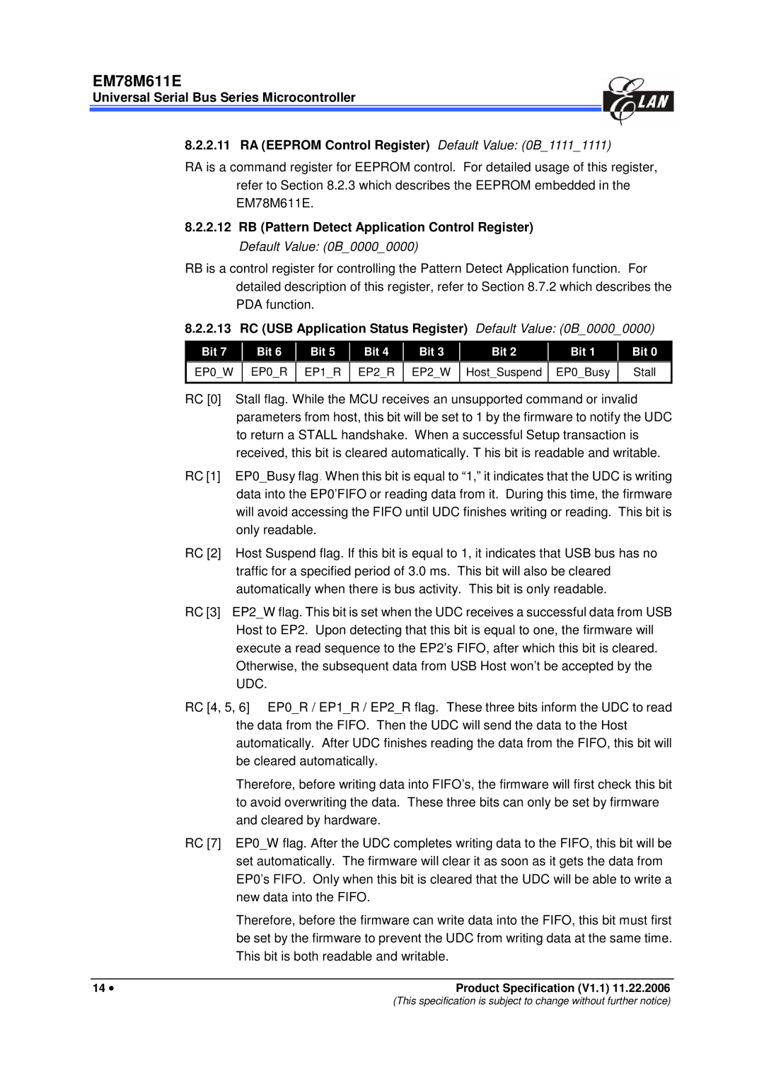
8.2.2.13 | RC (USB Application Status Register) Default Value: (0B_0000_0000) | |||||||||||||
|
|
|
|
|
|
|
|
|
|
|
|
|
|
|
Bit 7 |
| Bit 6 |
| Bit 5 |
| Bit 4 |
| Bit 3 |
| Bit 2 |
| Bit 1 |
| Bit 0 |
|
|
|
|
|
|
|
|
|
|
|
|
|
|
|
EP0_W |
| EP0_R |
| EP1_R | EP2_R |
| EP2_W |
| Host_Suspend |
| EP0_Busy | Stall | ||
|
|
|
|
|
|
|
|
|
|
|
|
|
|
|
RC [0] Stall flag. While the MCU receives an unsupported command or invalid parameters from host, this bit will be set to 1 by the firmware to notify the UDC to return a STALL handshake. When a successful Setup transaction is received, this bit is cleared automatically. T his bit is readable and writable.
RC [1] EP0_Busy flag. When this bit is equal to “1,” it indicates that the UDC is writing data into the EP0’FIFO or reading data from it. During this time, the firmware will avoid accessing the FIFO until UDC finishes writing or reading. This bit is only readable.
RC [2] Host Suspend flag. If this bit is equal to 1, it indicates that USB bus has no traffic for a specified period of 3.0 ms. This bit will also be cleared automatically when there is bus activity. This bit is only readable.
RC [3] EP2_W flag. This bit is set when the UDC receives a successful data from USB Host to EP2. Upon detecting that this bit is equal to one, the firmware will execute a read sequence to the EP2’s FIFO, after which this bit is cleared. Otherwise, the subsequent data from USB Host won’t be accepted by the UDC.
RC [4, 5, 6] EP0_R / EP1_R / EP2_R flag. These three bits inform the UDC to read the data from the FIFO. Then the UDC will send the data to the Host automatically. After UDC finishes reading the data from the FIFO, this bit will be cleared automatically.
Therefore, before writing data into FIFO’s, the firmware will first check this bit to avoid overwriting the data. These three bits can only be set by firmware and cleared by hardware.
RC [7] EP0_W flag. After the UDC completes writing data to the FIFO, this bit will be set automatically. The firmware will clear it as soon as it gets the data from EP0’s FIFO. Only when this bit is cleared that the UDC will be able to write a new data into the FIFO.
Therefore, before the firmware can write data into the FIFO, this bit must first be set by the firmware to prevent the UDC from writing data at the same time. This bit is both readable and writable.
14 • | Product Specification (V1.1) 11.22.2006 |
(This specification is subject to change without further notice)
