EM78M611E
Universal Serial Bus Series Microcontroller
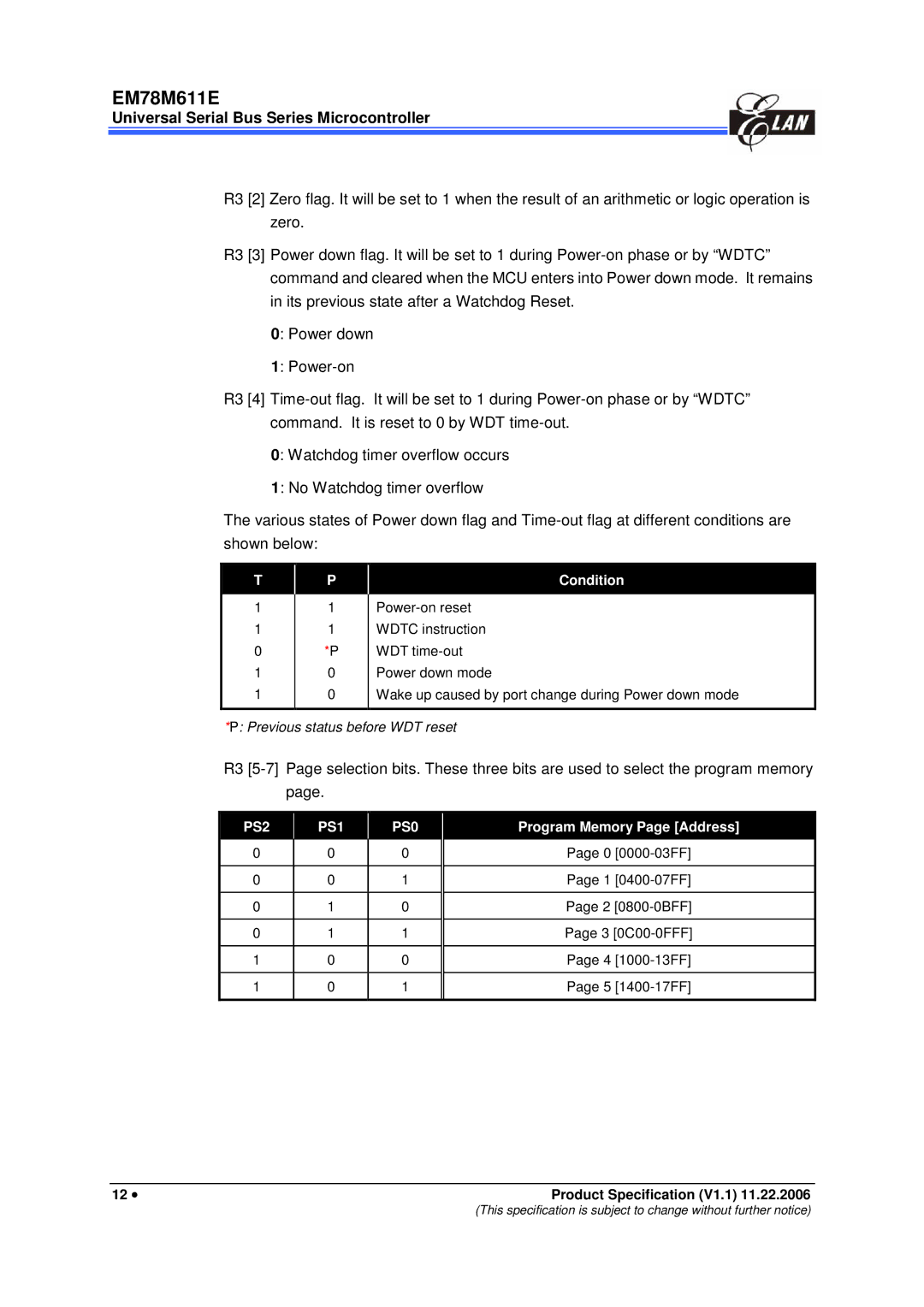
R3 [2] Zero flag. It will be set to 1 when the result of an arithmetic or logic operation is zero.
R3 [3] Power down flag. It will be set to 1 during
0: Power down
1:
R3 [4]
0: Watchdog timer overflow occurs
1: No Watchdog timer overflow
The various states of Power down flag and
T | P | Condition |
|
|
|
1
1
0
1
1
1
1 *P 0 0
Wake up caused by port change during Power down mode
*P: Previous status before WDT reset
R3
PS2 | PS1 | PS0 | Program Memory Page [Address] | |
|
|
|
| |
0 | 0 | 0 | Page 0 | |
|
|
|
| |
0 | 0 | 1 | Page 1 | |
|
|
|
| |
0 | 1 | 0 | Page 2 | |
|
|
|
| |
0 | 1 | 1 | Page 3 | |
|
|
|
| |
1 | 0 | 0 | Page 4 | |
|
|
|
| |
1 | 0 | 1 | Page 5 | |
|
|
|
|
12 • | Product Specification (V1.1) 11.22.2006 |
(This specification is subject to change without further notice)
