4. REFRIGERANT FLOW DIAGRAM
4-1. Refrigerant Flow Diagram
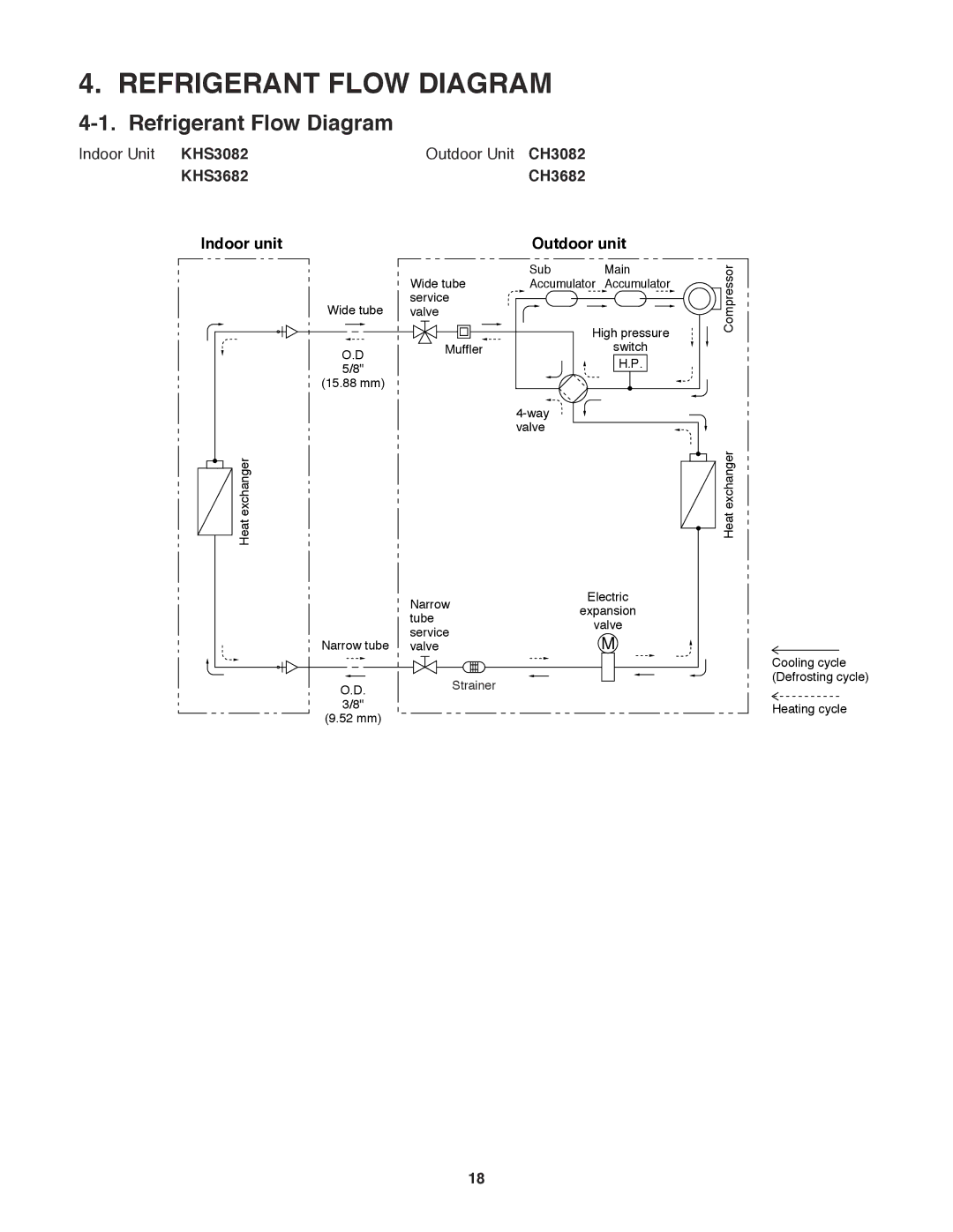
Indoor Unit KHS3082 | Outdoor Unit CH3082 |
KHS3682 | CH3682 |
Indoor unit | Outdoor unit |
|
| Sub | Main | Compressor |
| Wide tube | Accumulator | Accumulator | |
Wide tube | service |
|
|
|
valve |
|
|
| |
|
| High pressure |
| |
O.D | Muffler |
| switch |
|
|
| H.P. |
| |
5/8" |
|
|
| |
(15.88 mm) |
|
|
|
|
|
|
|
| |
|
| valve |
|
|
Heat exchanger |
|
|
| Heat exchanger |
| Narrow | Electric |
| |
| expansion |
| ||
| tube |
| ||
| valve |
| ||
| service |
| ||
Narrow tube |
| M |
| |
valve |
|
| ||
O.D. | Strainer |
|
|
|
3/8" |
|
|
|
|
(9.52 mm) |
|
|
|
|
Cooling cycle (Defrosting cycle)
Heating cycle
18