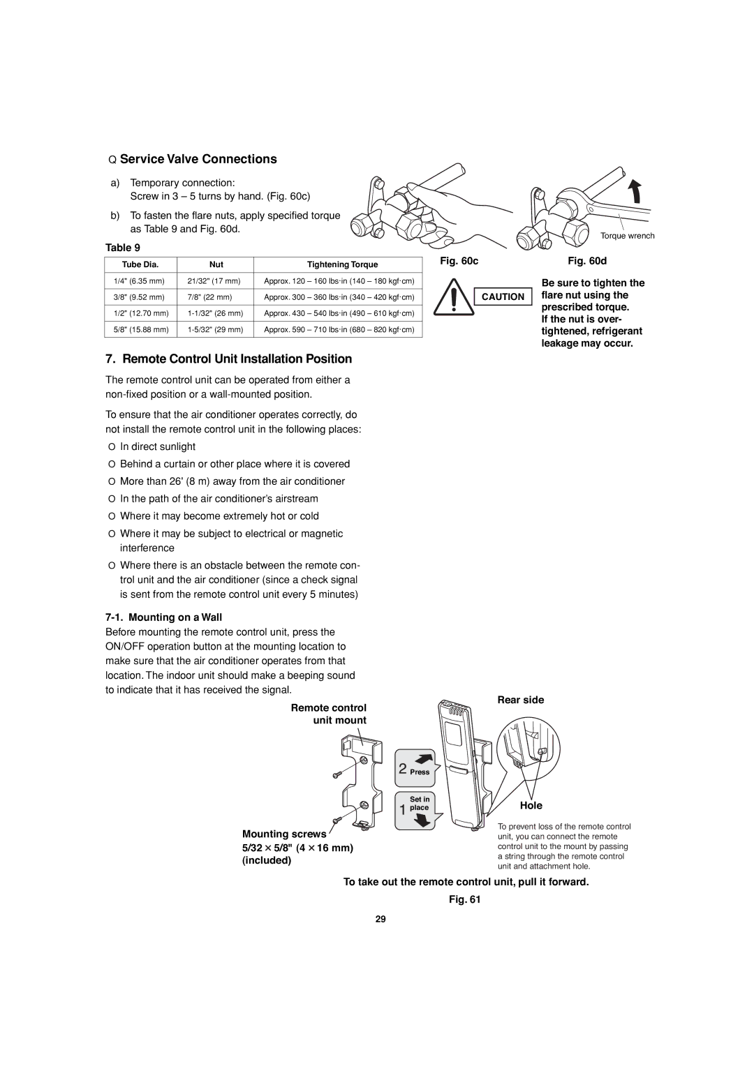
■Service Valve Connections
a)Temporary connection:
Screw in 3 – 5 turns by hand. (Fig. 60c)
b)To fasten the flare nuts, apply specified torque as Table 9 and Fig. 60d.
Table 9
Tube Dia. | Nut | Tightening Torque |
|
|
|
1/4" (6.35 mm) | 21/32" (17 mm) | Approx. 120 – 160 lbs·in (140 – 180 kgf·cm) |
|
|
|
3/8" (9.52 mm) | 7/8" (22 mm) | Approx. 300 – 360 lbs·in (340 – 420 kgf·cm) |
|
|
|
1/2" (12.70 mm) | Approx. 430 – 540 lbs·in (490 – 610 kgf·cm) | |
|
|
|
5/8" (15.88 mm) | Approx. 590 – 710 lbs·in (680 – 820 kgf·cm) | |
|
|
|
Fig. 60c
CAUTION
Torque wrench
Fig. 60d
Be sure to tighten the flare nut using the prescribed torque.
If the nut is over- tightened, refrigerant leakage may occur.
7. Remote Control Unit Installation Position
The remote control unit can be operated from either a
To ensure that the air conditioner operates correctly, do not install the remote control unit in the following places:
●In direct sunlight
●Behind a curtain or other place where it is covered
●More than 26' (8 m) away from the air conditioner
●In the path of the air conditioner’s airstream
●Where it may become extremely hot or cold
●Where it may be subject to electrical or magnetic interference
●Where there is an obstacle between the remote con- trol unit and the air conditioner (since a check signal is sent from the remote control unit every 5 minutes)
7-1. Mounting on a Wall
Before mounting the remote control unit, press the ON/OFF operation button at the mounting location to make sure that the air conditioner operates from that location. The indoor unit should make a beeping sound to indicate that it has received the signal.
Remote control unit mount
![]() Press
Press
Set in place
Mounting screws
5/32  5/8" (4
  16 mm) (included)
Rear side
Hole
To prevent loss of the remote control unit, you can connect the remote control unit to the mount by passing a string through the remote control unit and attachment hole.
To take out the remote control unit, pull it forward.
Fig. 61
29
