EM78M611E
Universal Serial Bus Series Microcontroller
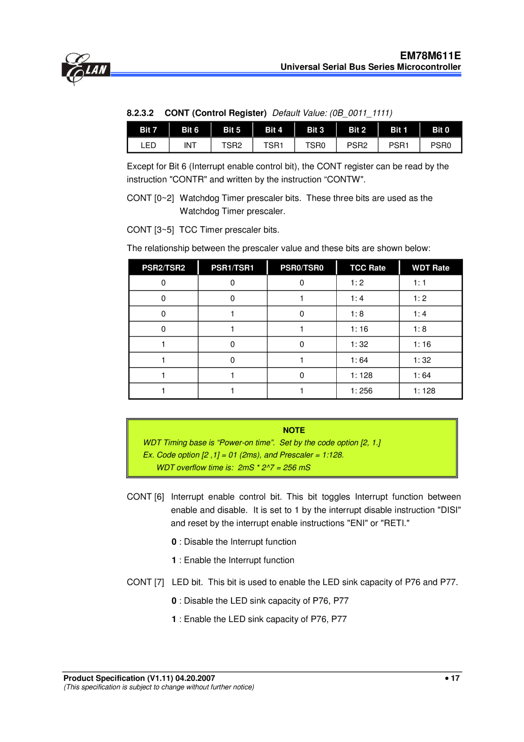
8.2.3.2CONT (Control Register) Default Value: (0B_0011_1111)
Bit 7 |
| Bit 6 |
| Bit 5 |
| Bit 4 |
| Bit 3 |
| Bit 2 |
| Bit 1 |
| Bit 0 |
|
|
|
|
|
|
|
|
|
|
|
|
|
|
|
LED |
| INT | TSR2 |
| TSR1 | TSR0 | PSR2 |
| PSR1 |
| PSR0 | |||
|
|
|
|
|
|
|
|
|
|
|
|
|
|
|
Except for Bit 6 (Interrupt enable control bit), the CONT register can be read by the instruction "CONTR" and written by the instruction “CONTW".
CONT [0~2] Watchdog Timer prescaler bits. These three bits are used as the Watchdog Timer prescaler.
CONT [3~5] TCC Timer prescaler bits.
The relationship between the prescaler value and these bits are shown below:
PSR2/TSR2 |
| PSR1/TSR1 |
| PSR0/TSR0 |
| TCC Rate |
| WDT Rate |
|
|
|
|
|
|
|
|
|
0 |
| 0 |
| 0 |
| 1: 2 |
| 1: 1 |
|
|
|
|
|
|
|
|
|
0 |
| 0 |
| 1 |
| 1: 4 |
| 1: 2 |
|
|
|
|
|
|
|
|
|
0 |
| 1 |
| 0 |
| 1: 8 |
| 1: 4 |
|
|
|
|
|
|
|
|
|
0 |
| 1 |
| 1 |
| 1: 16 |
| 1: 8 |
|
|
|
|
|
|
|
|
|
1 |
| 0 |
| 0 |
| 1: 32 |
| 1: 16 |
|
|
|
|
|
|
|
|
|
1 |
| 0 |
| 1 |
| 1: 64 |
| 1: 32 |
|
|
|
|
|
|
|
|
|
1 |
| 1 |
| 0 |
| 1: 128 |
| 1: 64 |
|
|
|
|
|
|
|
|
|
1 |
| 1 |
| 1 |
| 1: 256 |
| 1: 128 |
|
|
|
|
|
|
|
|
|
NOTE
WDT Timing base is
Ex. Code option [2 ,1] = 01 (2ms), and Prescaler = 1:128.
WDT overflow time is: 2mS * 2^7 = 256 mS
CONT [6] Interrupt enable control bit. This bit toggles Interrupt function between enable and disable. It is set to 1 by the interrupt disable instruction "DISI" and reset by the interrupt enable instructions "ENI" or "RETI."
0 : Disable the Interrupt function
1 : Enable the Interrupt function
CONT [7] LED bit. This bit is used to enable the LED sink capacity of P76 and P77.
0 : Disable the LED sink capacity of P76, P77
1 : Enable the LED sink capacity of P76, P77
Product Specification (V1.11) 04.20.2007 | • 17 |
(This specification is subject to change without further notice)